Jens Larsen's small 10.5" bandsaw
 Jens Larsen writes:
I've finally gotten around to making a bandsaw.
I have a medium size saw, a decent English one, which I use a lot for rough work. It's mostly fitted with a wide, and often well-worn blade (cutting through bark doesn't do it any good). So having a smaller one with a narrow blade is something I had wanted for some time.
As my saw had to be small enough to stand on a workbench and to be moved easily, one of your plans was not an option. But being much impressed by your bandsaws, I did take the liberty to base my design on yours.
I chose a wheel diameter of 270mm (10½") and a blade speed of about 700 m/min. Using a 1400 rpm motor I had laying around, it ought to be possible to fit the motor inside the frame.
This would, I thought, make the machine more portable. Construction could be made simpler by forming the bottom part of the frame with 3 pieces of plywood, one at each end of the frame, and one between these to give stiffness crosswise.
It worked well on paper. Replacing the front-most board in the lower frame member with a thinner piece of 12 mm plywood, gave room for a slightly thicker hub/pulley on the lower wheel. Letting the trunnions for the table tilt sit directly on the lower frame member didn't leave much room for the bottom blade support, but just enough.
The rest is much like your saws. The frame is of course scaled down. More than adequate for the small saw, even with slightly simpler design.
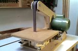
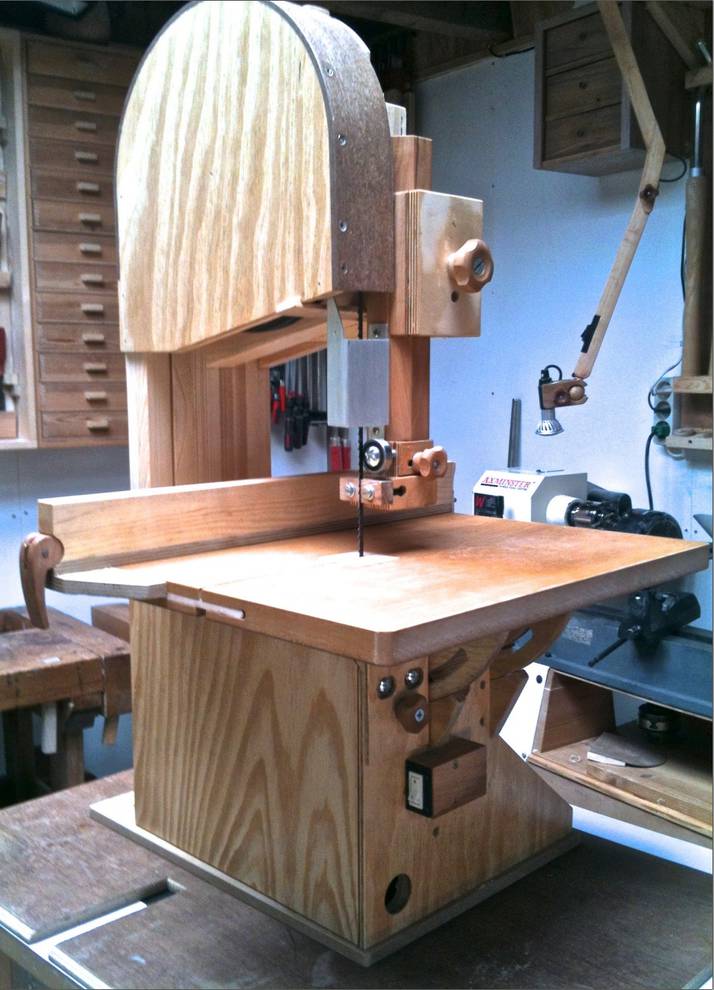 The finished saw with fence in place. I didn't have enough decent
plywood at hand for the table, so it's made from an old veneered MDF
tabletop. Works quite well, and the piece of hardwood inserted at the
front to keep the parts aligned isn't really necessary.
The finished saw with fence in place. I didn't have enough decent
plywood at hand for the table, so it's made from an old veneered MDF
tabletop. Works quite well, and the piece of hardwood inserted at the
front to keep the parts aligned isn't really necessary.
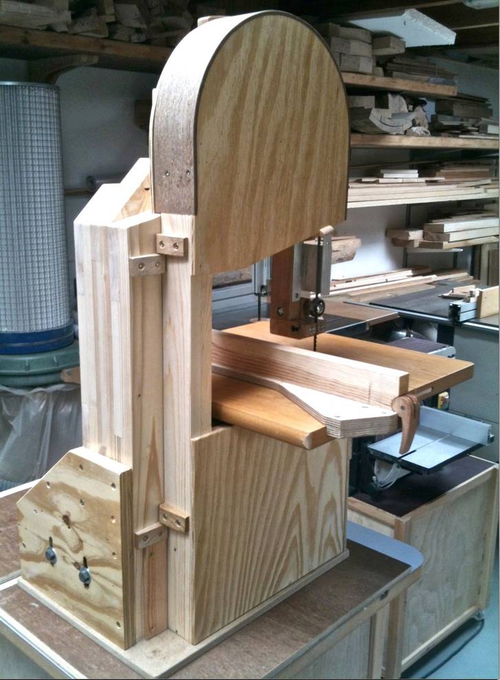
The upper blade guide is made much like yours, except that it's cut from one block of ply, and that I fastened the guide-blocks with barrel-nuts rather than making slots in the guide-blocks. To ease alignment it has a small ledge for these to rest on (same is done on the lower ones)
I won't win any safety-points for the guard, I'm afraid, but it's safe enough. It's only partly open with the guide in a low position, and I can't see how a jumped-off or broken blade should escape anyway. I made it this small, to avoid having it go through the top of the enclosure.
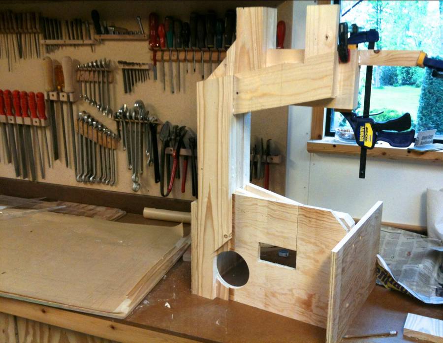 After glue-up. the frame was cut to size on the table saw, and the
plywood end plates forming the bottom frame test fitted. An extra piece
was glued on to give a better support to the upper blade-guide column.
After glue-up. the frame was cut to size on the table saw, and the
plywood end plates forming the bottom frame test fitted. An extra piece
was glued on to give a better support to the upper blade-guide column.
 The frame is made from five 18x90 mm construction quality pine, with
one board in the upper member being 120mm. A further board is added to
the upright, and the outer board on the lower member is replaced by 12mm
ply + 6 mm infill.
The frame is made from five 18x90 mm construction quality pine, with
one board in the upper member being 120mm. A further board is added to
the upright, and the outer board on the lower member is replaced by 12mm
ply + 6 mm infill.
I'm not into CAD design, so mine was done the old fashioned way with pencil and T-square. Quite fast and accurate, and all on one piece of packing paper as seen on the left.
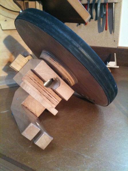
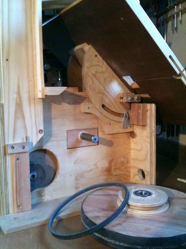
 The wheels are made from 18 mm, + a 12 mm rim, of rather inferior ply,
and with hubs of Baltic birch ply.
The wheels are made from 18 mm, + a 12 mm rim, of rather inferior ply,
and with hubs of Baltic birch ply.
I have a good size lathe and a chuck that can grip inside a 35 mm hole, so I made the wheels by first turning the hub/pulley from 24 mm ply, Then I glued everything up and finished the wheels on the lathe, including the recesses for the 40mm bearings.
Bicycle tubes don't come this small, so I had to use some other tubes and glue them on (with Superglue) to make them stay in place.
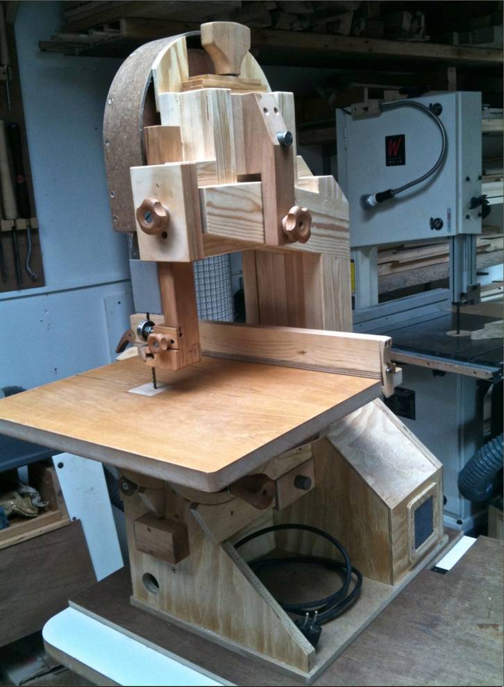 I liked your second design for
supporting the upper wheel,
but had to
turn it "upside-down" to fit neatly with my smaller wheels. That is I
made one of the boards in the frame 30 mm higher than the rest and cut a slot in the
bottom of the block to fit over this. This also brought the "pivot point" much
closer to the axle, which should, in principle, be an advantage. And for
the same reason, space restraints, I made the block of two parts, the
rear-most of which I let pass down behind the frame, allowing the tilt
alignment to act directly on the frame.
Tilt adjustment is by a hanger-bolt screwed into the frame.
I liked your second design for
supporting the upper wheel,
but had to
turn it "upside-down" to fit neatly with my smaller wheels. That is I
made one of the boards in the frame 30 mm higher than the rest and cut a slot in the
bottom of the block to fit over this. This also brought the "pivot point" much
closer to the axle, which should, in principle, be an advantage. And for
the same reason, space restraints, I made the block of two parts, the
rear-most of which I let pass down behind the frame, allowing the tilt
alignment to act directly on the frame.
Tilt adjustment is by a hanger-bolt screwed into the frame.
 I didn't want anything to protrude above the enclosure, so made a
spade-like handle rather than a crank. Not as handy but it works well
enough.
I didn't want anything to protrude above the enclosure, so made a
spade-like handle rather than a crank. Not as handy but it works well
enough.
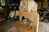
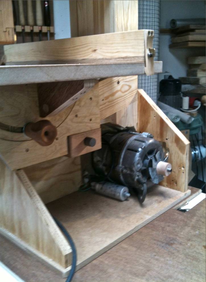 The motor is from a very old washing machine. And it's quite open, so I
had to add a fan, and a filter to the enclosure, to keep it cool and
dust free (see previous photo).
The motor is from a very old washing machine. And it's quite open, so I
had to add a fan, and a filter to the enclosure, to keep it cool and
dust free (see previous photo).
The motor is bolted directly to the side panel, but I got the belt length a bit wrong, so had to lay it a bit into the panel to get enough room for adjustment.
For added stiffness a bracket is added between the trunnion and the table at the rear.
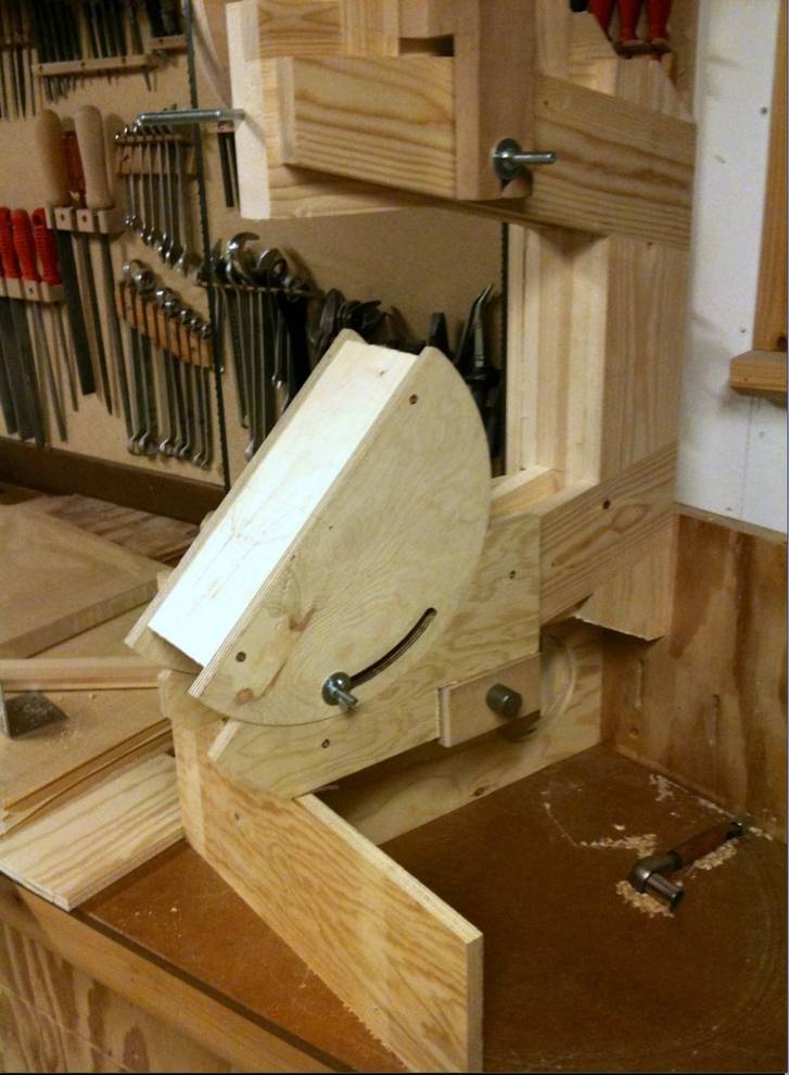 The trunnions were cut on the bandsaw from good quality 12 mm ply, sanded
to fit, and test fitted to ensure proper position and function. They are
held in position by a 10 mm coach bolt through the frame. The bolt is
held in position (if not, it tends to act as a brake ) by the small
aluminum plate seen behind the blade guide in the next picture.
The trunnions were cut on the bandsaw from good quality 12 mm ply, sanded
to fit, and test fitted to ensure proper position and function. They are
held in position by a 10 mm coach bolt through the frame. The bolt is
held in position (if not, it tends to act as a brake ) by the small
aluminum plate seen behind the blade guide in the next picture.
 Screws into the side of 12 mm ply didn't hold very well, so a 16 mm dowel is
inserted to receive the lower screw from the side panel.
Screws into the side of 12 mm ply didn't hold very well, so a 16 mm dowel is
inserted to receive the lower screw from the side panel.
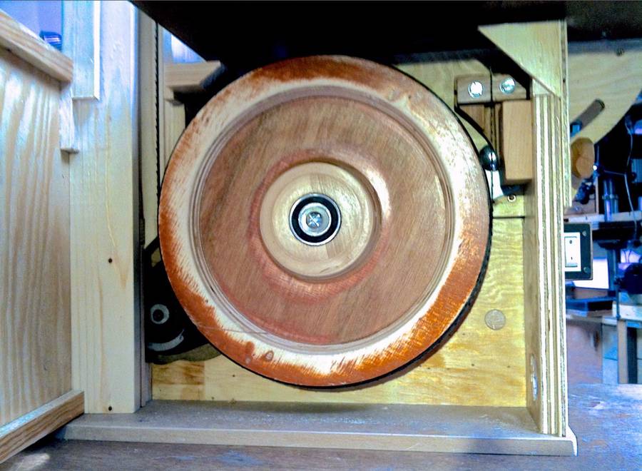
There isn't much room for the pulley, belt and cover-plate, but just enough. But getting everything in place with a belt that's too short to go around the main wheel, the limited space, and a tight fitting cover plate is a bit tricky.

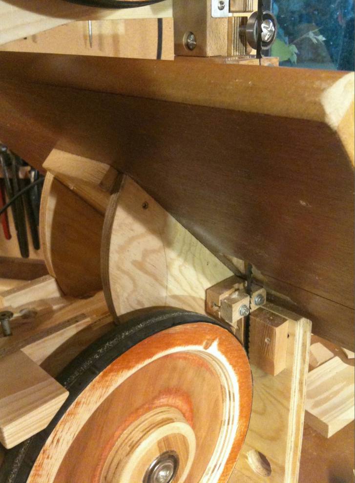 The lower blade-guide holder is made of one piece of hardwood, and is
quite complicated.
The lower blade-guide holder is made of one piece of hardwood, and is
quite complicated.
Its held to the side by 2 bolts threaded into the holder and running in a slot in the side panel. The arrangement is tight, but does allow for the adjustment needed.
See also:
 Jens Larsen's strip sander
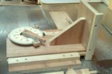 Jens Larsen's tenon jig
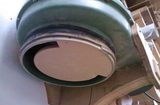 Jens Larsen's dust
collector Thien-baffle
modifications
 More reader built
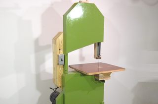 Homemade 16" bandsaw
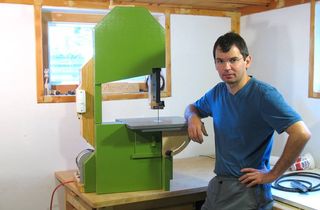 Homemade 14" bandsaw