 Having made two small projects on my
homemade lathe, there were already several
improvements I wanted to make.
Having made two small projects on my
homemade lathe, there were already several
improvements I wanted to make.
Having made two small projects on my
homemade lathe, there were already several
improvements I wanted to make.
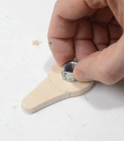
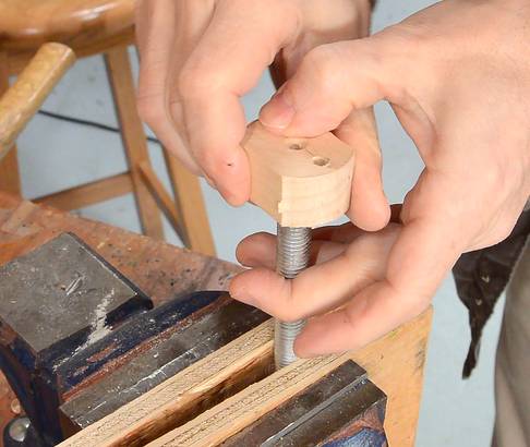
 The first change was to make a handle for the nut so I wouldn't
need a wrench to adjust the tool rest.
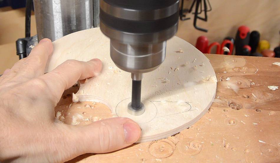
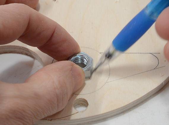
I started by drilling a hole the same diameter as the nut is
flat-to-flat, then marked the outline of the nut around the hole.
The first change was to make a handle for the nut so I wouldn't
need a wrench to adjust the tool rest.
I started by drilling a hole the same diameter as the nut is
flat-to-flat, then marked the outline of the nut around the hole.
I filed the hole hexagonal, but slightly smaller than the nut.
I tightened the nut on the tool rest by about as much as I usually do
and marked which side of the nut faced left. I then put the nut on
the hole, with the side facing left towards the handle and hammered
it into the hole using a piece of wood.

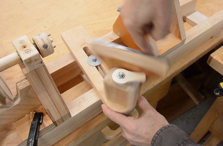 The handle prevents me from spinning the nut freely,
but I can spin the whole tool rest with the nut and handle
until the nut is threaded down as far as I needed.
The handle prevents me from spinning the nut freely,
but I can spin the whole tool rest with the nut and handle
until the nut is threaded down as far as I needed.
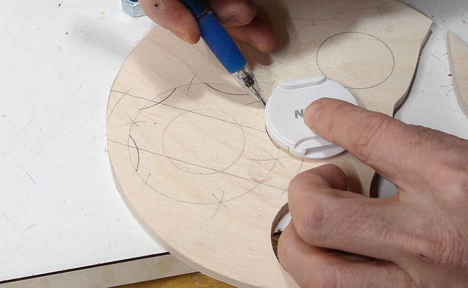
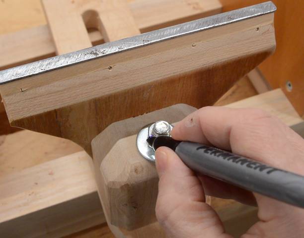
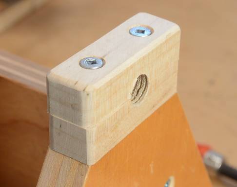
 I also made a knob for the nut that holds the tool rest onto the lathe
using the same method, but this one is more of a star knob.
I also made a knob for the nut that holds the tool rest onto the lathe
using the same method, but this one is more of a star knob.
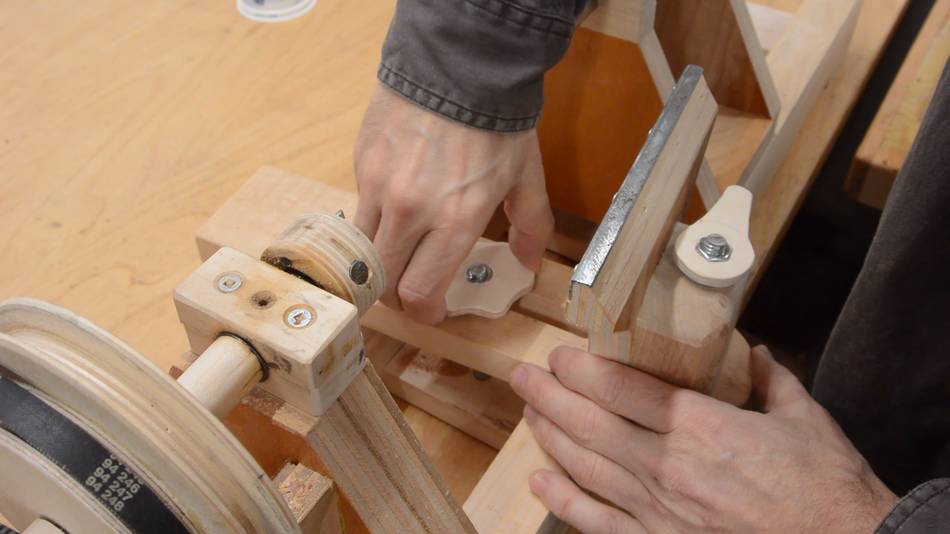 Putting the new knob on.
 The lathe made a rattling sound when it ran. I realized this
came from the spacers that I made for each side of the pulley.
They were loose and rattled as they turned.
The lathe made a rattling sound when it ran. I realized this
came from the spacers that I made for each side of the pulley.
They were loose and rattled as they turned.
They were tricky to get right and the shaft still had some lateral play even with them, so I figured they weren't the best solution. They also prevent me from checking if the shaft is hot, which, with wooden bearings, I want to be able to check.

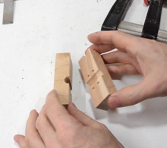 So I made a block to clamp to the far end of the shaft to lock
it in place. I made this block much like I made the bearing blocks,
but with a hole a tiny bit smaller than the shaft.
So I made a block to clamp to the far end of the shaft to lock
it in place. I made this block much like I made the bearing blocks,
but with a hole a tiny bit smaller than the shaft.
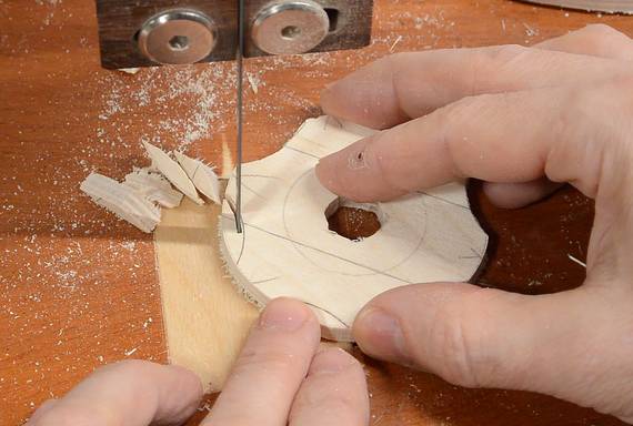
First I drilled the screw holes through it, then cut a block in half, then clamped the two halves together and drilled the hole on the line between the two.
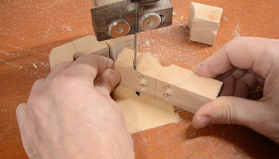 After that, I cut it roughly round on the bandsaw.
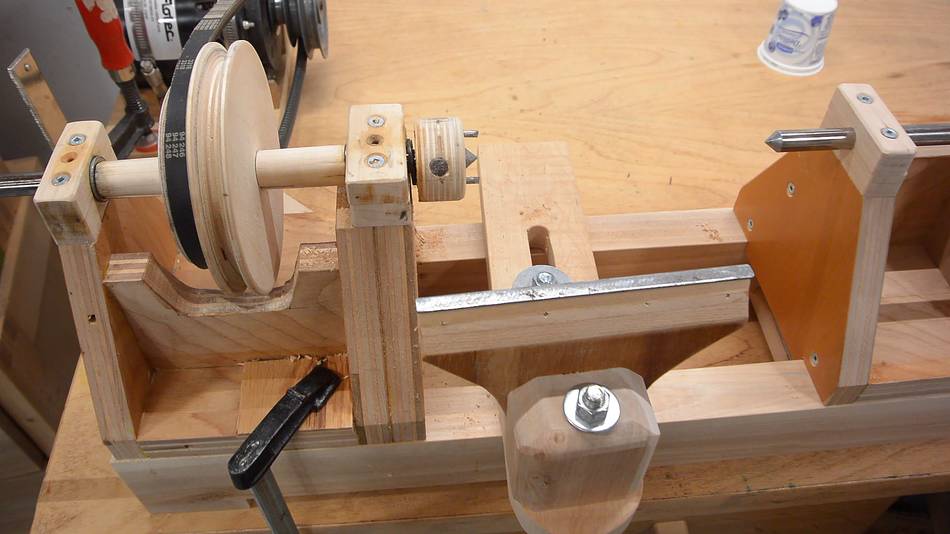
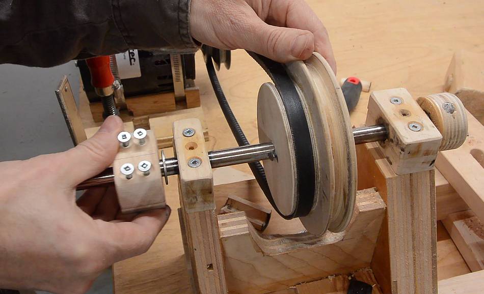 Then sliding the block in place, with a washer between it and the
bearing block. With this block tightened on the shaft, the main
shaft is no longer able to move side-to-side.
Then sliding the block in place, with a washer between it and the
bearing block. With this block tightened on the shaft, the main
shaft is no longer able to move side-to-side.
 I wanted a better way to move the shaft on the tailstock forward. So
far, I nudged it tighter by tapping the back with a mallet. But with
only friction holding it in place, I figured there is risk of it
slipping back unexpectedly and releasing the workpiece. That would be
bad.
I wanted a better way to move the shaft on the tailstock forward. So
far, I nudged it tighter by tapping the back with a mallet. But with
only friction holding it in place, I figured there is risk of it
slipping back unexpectedly and releasing the workpiece. That would be
bad.
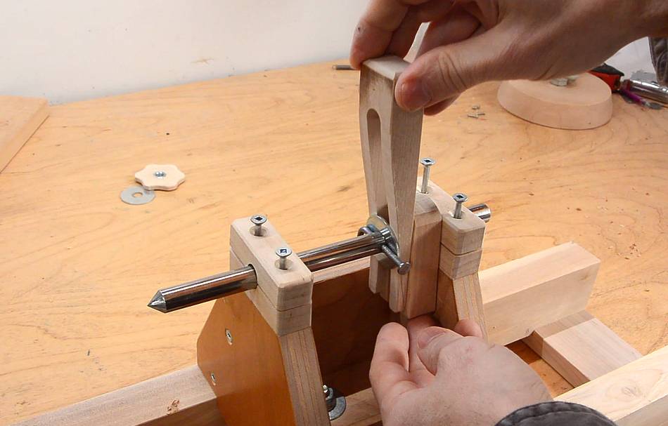
My first idea was to put a pin (a nail) through the shaft, and then use spacer blocks and wedges to drive the shaft forward. But I realized, if the wedge is relatively high up (as shown), with vibrations, the wedge could tip forward and then fall out. This would allow the tailstock shaft to move back suddenly. Not safe.
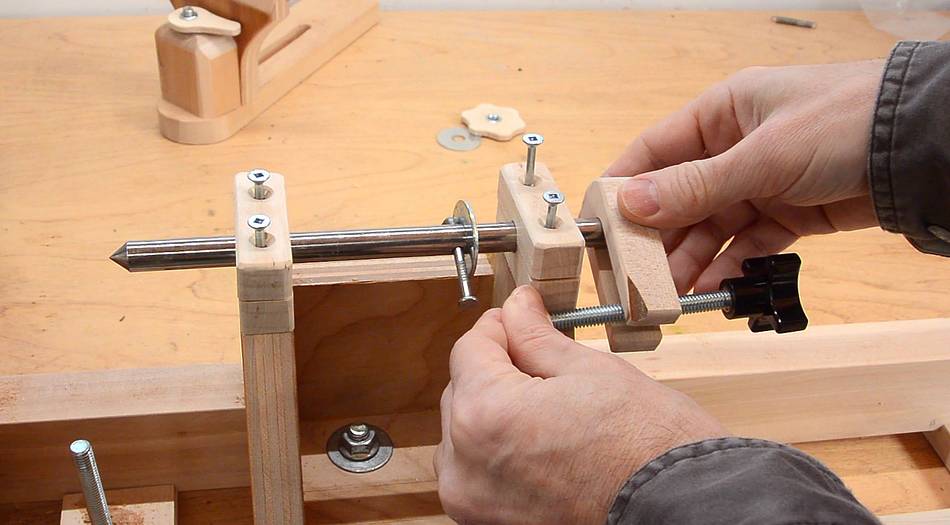 My next idea was to have a bolt next to the shaft. A knob on the bolt would pull
a block attached to the end of the shaft forward as the knob is tightened.
My next idea was to have a bolt next to the shaft. A knob on the bolt would pull
a block attached to the end of the shaft forward as the knob is tightened.
But that approach also has its hazards. With a lot of friction on the shaft, the knob could work itself loose without loosening the workpiece, and the shaft could then jump back unexpectedly. Also unsafe.
 I wanted to keep using the smooth shaft because I managed to make a
perfect point on the end of it by mounting the shaft in the headstock
and grinding it as it turned.
I wanted to keep using the smooth shaft because I managed to make a
perfect point on the end of it by mounting the shaft in the headstock
and grinding it as it turned.
I thought I couldn't really do that with the threaded rod because the threads would chew up the bearings. But I gave it a try. I made a block to attach to the end of the threaded rod to mate with the drive center on the headstock. I also made a sacrificial bearing block, which I clamped to the tailstock. Two nuts on the threaded rod against the bearing block keep it pressed against the headstock.

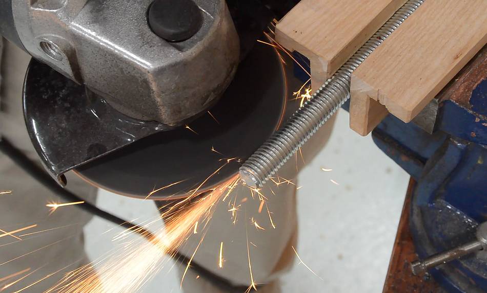
 I then used an angle grinder to grind a point on it. This worked better
than I expected. After that, I used a fine file to smooth
the cone and polished it on a buffing wheel.
I then used an angle grinder to grind a point on it. This worked better
than I expected. After that, I used a fine file to smooth
the cone and polished it on a buffing wheel.
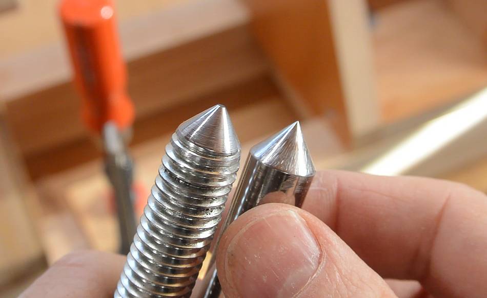 The resulting cone was as good as the one I made on the shaft earlier.
I should have tried that in the first place.
The resulting cone was as good as the one I made on the shaft earlier.
I should have tried that in the first place.
 I then used an angle grinder to grind a keyway in the other end of
the threaded rod.
I then used an angle grinder to grind a keyway in the other end of
the threaded rod.
 The sharp edges of the keyway were ideal for cutting a thread in the blocks
on the tailstock. The hole in these blocks was about 1 mm smaller than the
outer diameter of the threaded rod.
The sharp edges of the keyway were ideal for cutting a thread in the blocks
on the tailstock. The hole in these blocks was about 1 mm smaller than the
outer diameter of the threaded rod.
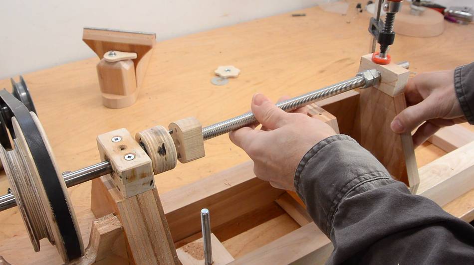
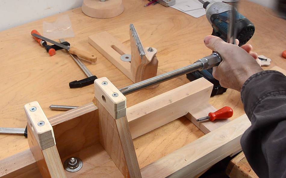
 I screwed the threaded rod all the way to the second block to grind a thread
into it that aligns with the first block.
I screwed the threaded rod all the way to the second block to grind a thread
into it that aligns with the first block.
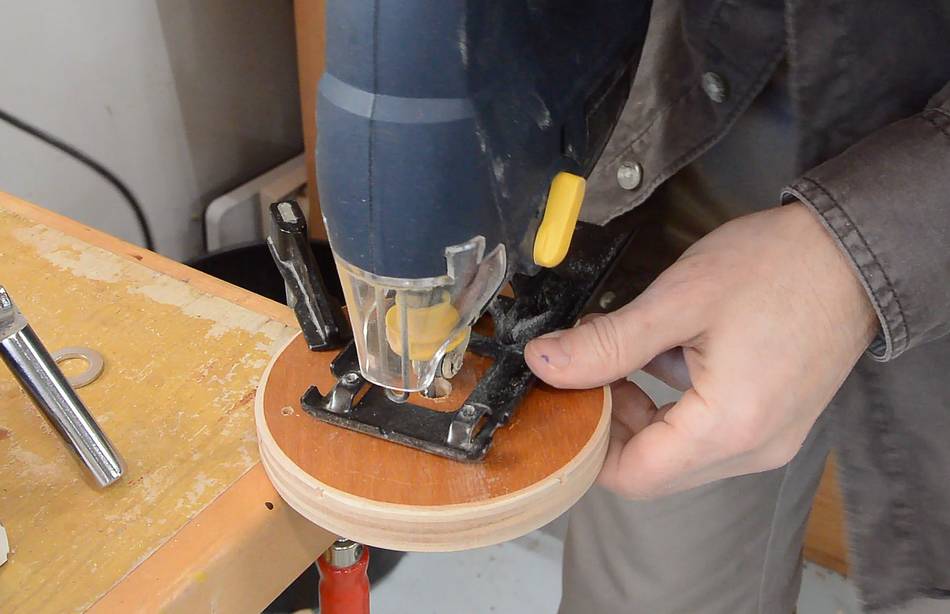 I cut out a disk to use as a crank on the tailstock, and used a jigsaw to cut a
keyway in the hole.
I cut out a disk to use as a crank on the tailstock, and used a jigsaw to cut a
keyway in the hole.
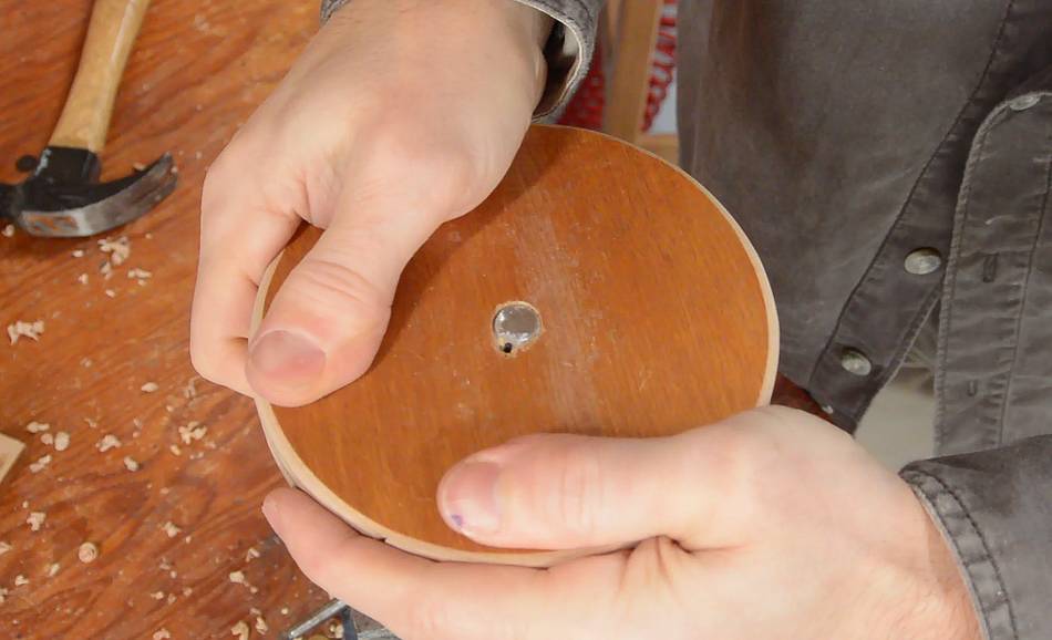
 The hole in my crank disk was also a bit smaller than the threaded rod.
I screwed it on until the threaded rod was flush with the disk and the
slots aligned. I screwed a small wood screw between the keyway notches
to lock it in place.
The hole in my crank disk was also a bit smaller than the threaded rod.
I screwed it on until the threaded rod was flush with the disk and the
slots aligned. I screwed a small wood screw between the keyway notches
to lock it in place.
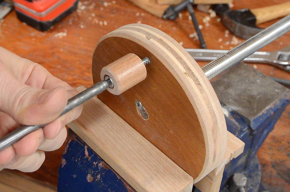 I also screwed a short piece of dowel onto the disk to act as a crank handle.

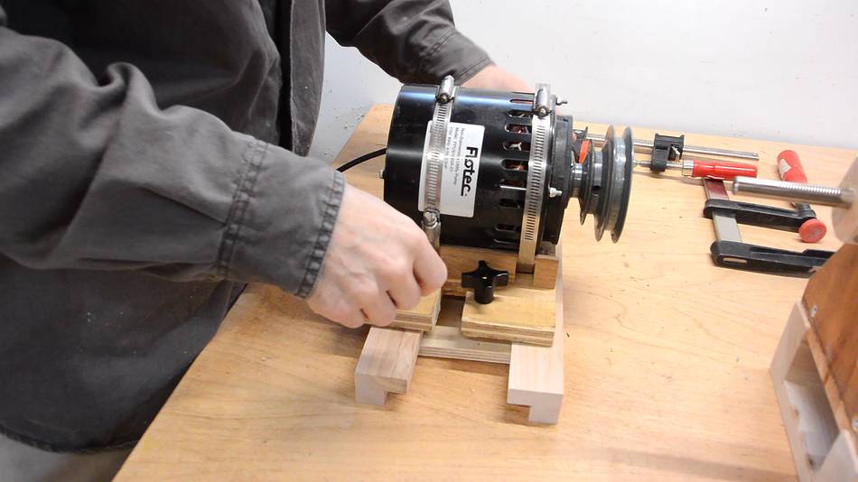
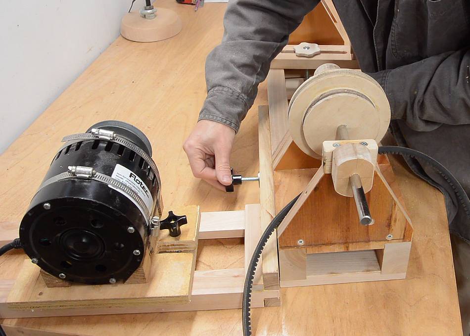
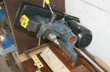
 The final improvement was to find a good way to mount the motor. I
wanted to be able to move the motor side-to-side and near and far
from the lathe so I could use all possible combinations of pulleys.
The final improvement was to find a good way to mount the motor. I
wanted to be able to move the motor side-to-side and near and far
from the lathe so I could use all possible combinations of pulleys.
The belt I'm using is perhaps a bit long for the job, but the advantage is that it keeps the motor further away from the shavings coming off the lathe.
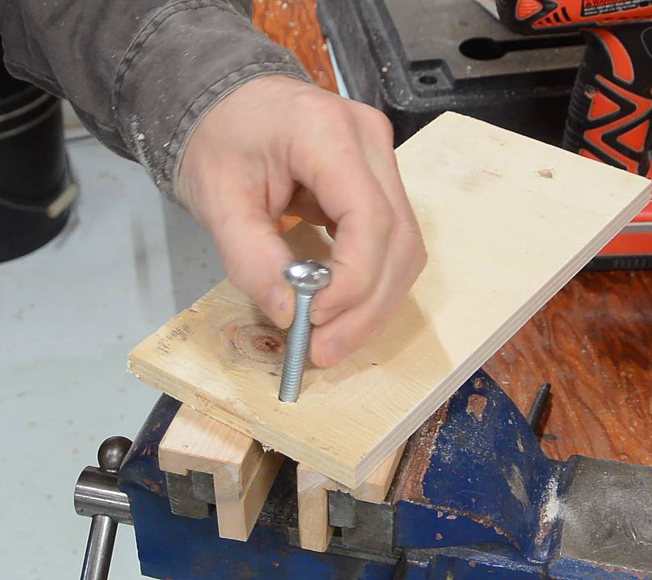
 I started by making two L-profiles out of wood on the table saw, and
a piece of plywood to go between them. This plywood has two carriage
bolts in it from below.
I started by making two L-profiles out of wood on the table saw, and
a piece of plywood to go between them. This plywood has two carriage
bolts in it from below.
 The motor is already on its own piece of plywood (from when I used
it to motorize
the apple grinder a few years ago).
The motor is already on its own piece of plywood (from when I used
it to motorize
the apple grinder a few years ago).
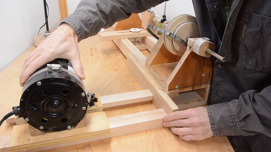 The L shaped rails allow the motor to move forwards and back. For
side-to-side adjustment, I figured it would be best to mortise them into
another piece of wood, which I could adjust side-to-side along the back
of the lathe.
The L shaped rails allow the motor to move forwards and back. For
side-to-side adjustment, I figured it would be best to mortise them into
another piece of wood, which I could adjust side-to-side along the back
of the lathe.
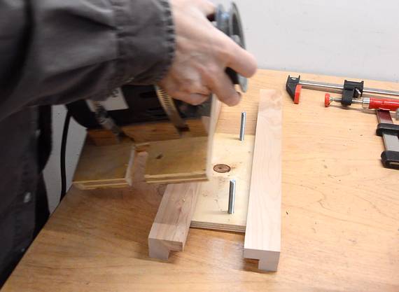
 I used a block of wood clamped to my table saw sled as a tenon jig to
cut a tenon on the ends of the L-shaped rails.
I used a block of wood clamped to my table saw sled as a tenon jig to
cut a tenon on the ends of the L-shaped rails.
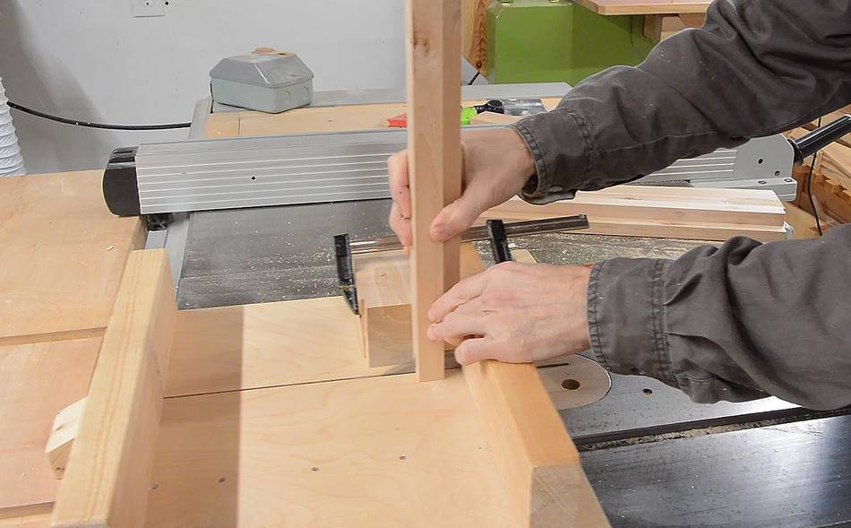
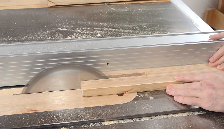 My slot mortiser would be ideal for cutting mortises into the board, but
I didn't want this project to be dependent on my custom machines. So I made
a series of cuts on the table saw to cut a sort of "open mortise" (like
here).
My slot mortiser would be ideal for cutting mortises into the board, but
I didn't want this project to be dependent on my custom machines. So I made
a series of cuts on the table saw to cut a sort of "open mortise" (like
here).
 Pieces inserted into the slot.
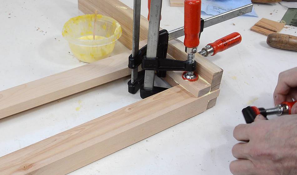 I made another block to go between the two pieces, then another to go
against the side of it to really stiffen up this joint.
I made another block to go between the two pieces, then another to go
against the side of it to really stiffen up this joint.
 Cutting a slot in the board to allow adjustment when it's mounted
to the lathe bed.
Cutting a slot in the board to allow adjustment when it's mounted
to the lathe bed.
 A carriage bolt through the back rail of the lathe bed, plus
washer and knob attach the board to the back of the lathe.
A carriage bolt through the back rail of the lathe bed, plus
washer and knob attach the board to the back of the lathe.
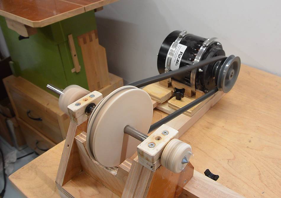 This is working nicely.
I'm sure people will suggest to just put the motor on a hinge so the motor's weight can tension the belt.
The problem with that is that V-belts are always prone to vibration. If the motor is hanging off the belt, that will cause the motor to shake. For every reaction there is an equal and opposite reaction, so shaking of the heavy motor will cause the whole lathe to shake. Not good.
But with the motor fixed to the lathe, the V-belt can only shake itself. The V-belt is much lighter than the motor, so it causes much less vibration in the lathe as a whole.
 Beri's homemade lathe
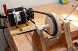 Building a lathe
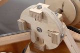 Homemade 4-jaw lathe chuck
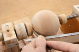 Ball on the lathe
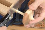 Spinning top on the lathe
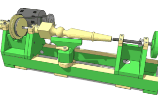 Buy the lathe plans
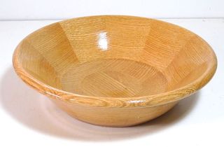 Bowl on the lathe
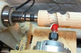 Brian Kerr's router lathe