Motorized wooden clock winder
This article contributed by Ron WaltersWinding wood gear clocks, especially those modified to run for 48 hours or longer can get tiring. The clock winder makes it easier and is especially useful for winding multiple clocks.
|

|
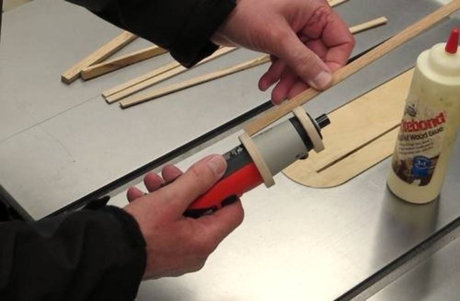
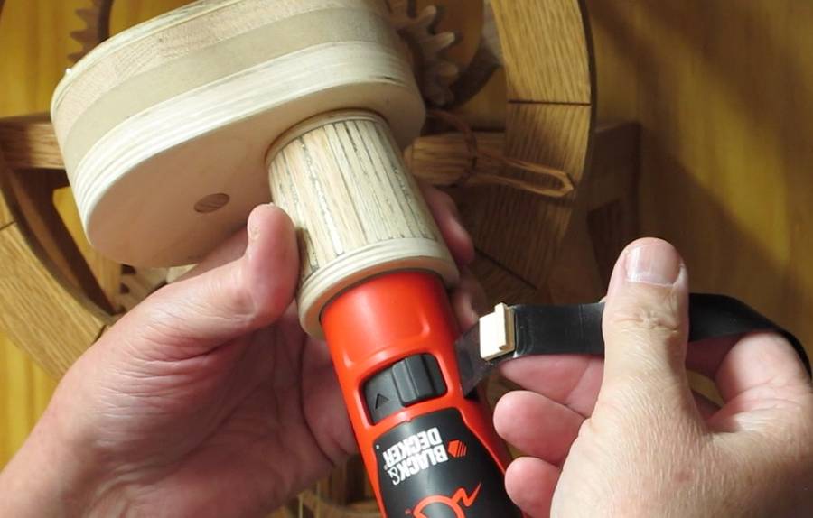
Construction starts with a couple of plywood rings with the inside surfaces tapered slightly so they fit snugly on the end of the cordless screwdriver (Black & Decker 2.4 Volt Model DP240 shown). Plastic wrap was placed over the screwdriver prior to assembly to prevent glue sticking to the screwdriver. Strips of wood cut to length and glued around the screwdriver to form the housing. The Slots were then filled with a mixture of sawdust and glue and the housing sanded smooth. The housing should fit firmly with a light twisting motion, no clamping required.
I fabricated a gearbox to suit the gears used, and attached it to the screwdriver housing.
|
|
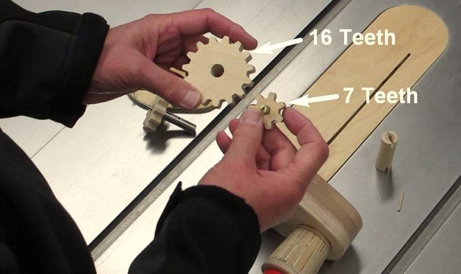
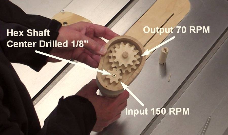
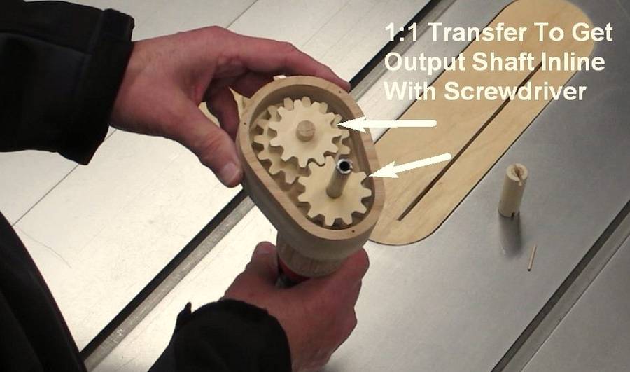
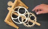
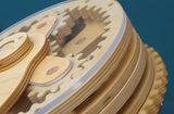
The screwdriver turns at 150 RPM, which is too fast for winding the clock. I used Matthias's Gear template program to make 16-tooth and 7-tooth gears to reduce the speed to 70 RPM. I really like the program feature, which allows you to select the shaft spacing. A hex shaft (center drilled 1/8") was epoxied into the pinion shaft.
|
|
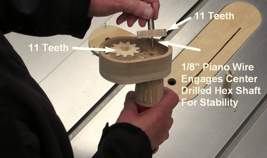
I wanted the output shaft to be inline with the screwdriver so it would be easy to use. I made two 11-tooth gears, one glued to the top of the 16-tooth gear and the other epoxied to the output shaft. A 1/8" piano wire was installed in the end of the output shaft. The 1/8" wire runs inside the hex shaft hole, holding the bottom of the output shaft in place. The top end of the output shaft is held by the gearbox lid. The two 11-tooth gears provide a 1:1 speed transfer and reverse the rotation to the original screwdriver direction of rotation.
 Trying to turn the clock winder in the wrong direction can damage the
clock. A piece of wood was made to keep the switch from accidentally
moving to the wrong location and is held in place with electrical tape.
Trying to turn the clock winder in the wrong direction can damage the
clock. A piece of wood was made to keep the switch from accidentally
moving to the wrong location and is held in place with electrical tape.

|

|
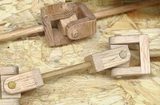
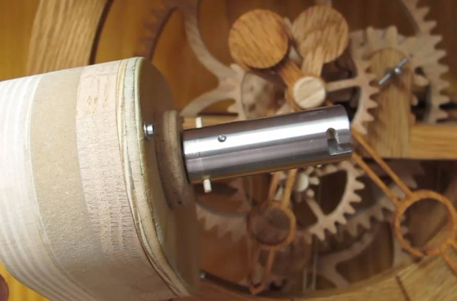 The J-Slot adapter locks onto the clock winder to prevent accidental
removal of the clock winder until the clock weight has been eased back
onto the clock winding click mechanism. The J-Slot provides 30 degrees
of engagement. The adapter is pinned to the output shaft making removal
or changing of the adapter quite easy.
The J-Slot adapter locks onto the clock winder to prevent accidental
removal of the clock winder until the clock weight has been eased back
onto the clock winding click mechanism. The J-Slot provides 30 degrees
of engagement. The adapter is pinned to the output shaft making removal
or changing of the adapter quite easy.
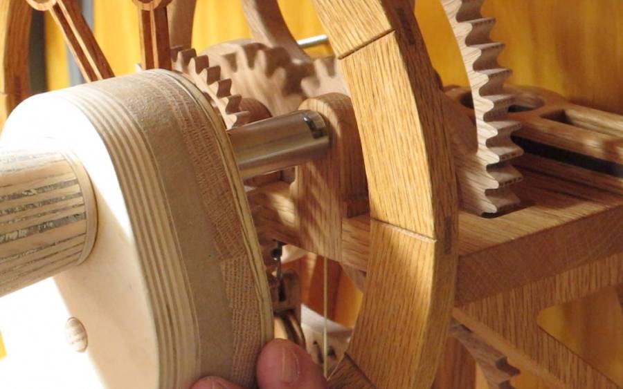 The J-Slot engages as soon as you start to wind the clock. When winding
is complete, gently turn the screwdriver handle conter clock wise easing the weight
back onto the clock click mechanism. Then turn the screwdriver slightly
further and remove the clock winder.
The J-Slot engages as soon as you start to wind the clock. When winding
is complete, gently turn the screwdriver handle conter clock wise easing the weight
back onto the clock click mechanism. Then turn the screwdriver slightly
further and remove the clock winder.
Other projects by Ronald Walters:
Various clock wheel building experiments |
Drill press table |
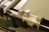 Table saw fence micro adjuster
|
Making wooden U-joints |
Planetary gear drive |