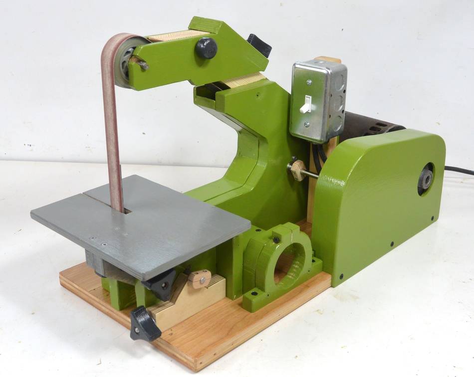
Ever since I built my strip sander
I quite like using it. I thought about building a second one,
but then I had the idea of building a bigger one using 1.5"x48" belts
instead of 1"x42" belts. I can cut these belts
from 6x48" sanding belts, especially sanding belts that are used up on my
6x48" belt sander
because there are usually some good parts of the belt left when
its done on that sander. Also a belt doesn't need to be as "sharp" for the kind
of use it gets on a strip sander.
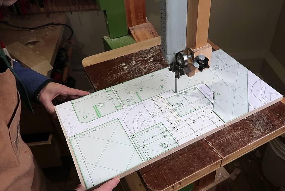
So I modified the CAD model of my 1x42" sander to accommodate the 1.5"x48" belt,
nested the 18 mm plywood parts closely together, printed out a 1:1 template
across several sheets using my bigprint program
and cut them out on my pretend CNC machine
(my 20" bandsaw)
After cutting the parts, I checked my timelapse camera. I was in the room with
the bandsaw for just 14 minutes, including setting up the camera and such.
My pretend CNC machine is faster than most hobby CNC machines.
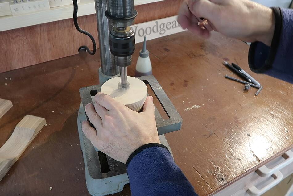
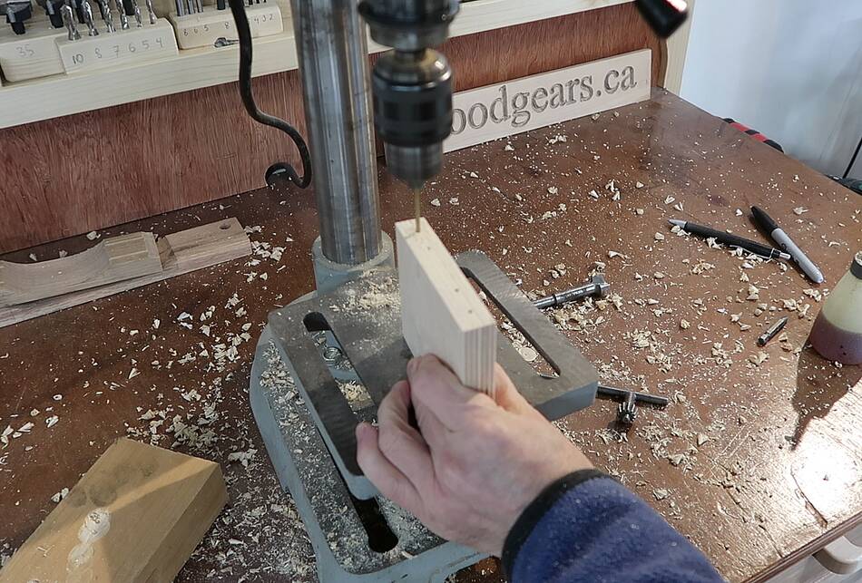
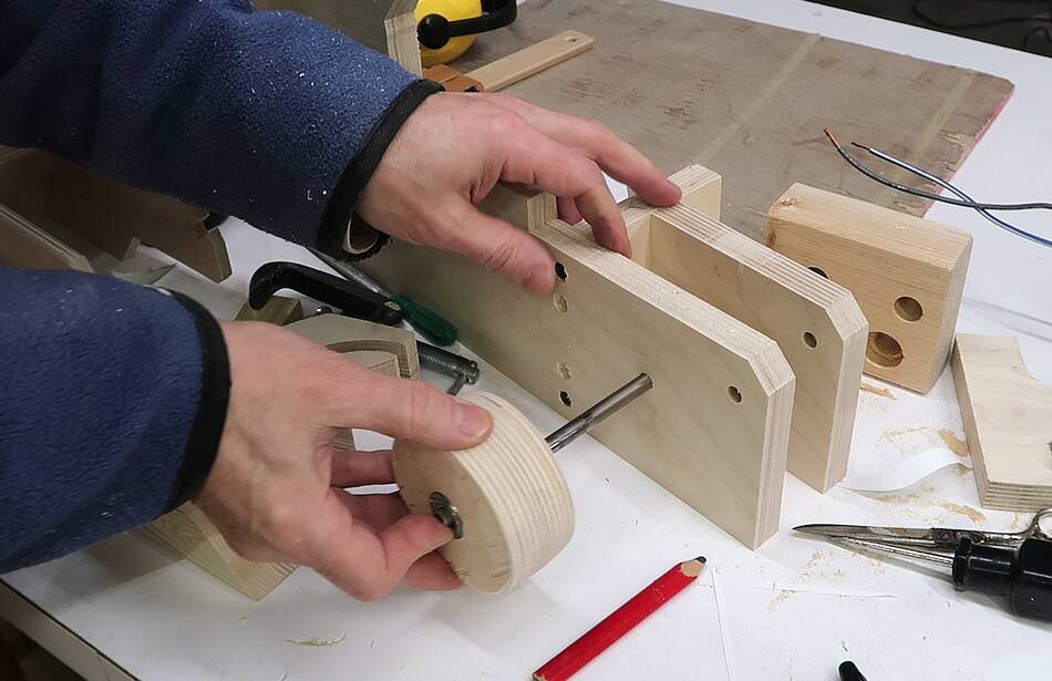
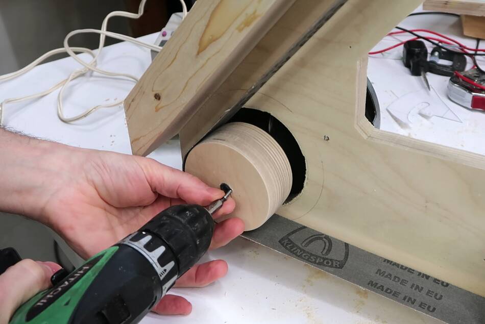
I previously glued some disks of 18mm plywood together for the wheels (also
cut out on the bandsaw). I want to seat some 22 mm roller skate bearing in them.
For this, I'm using a custom sized drill
which makes for a tight fit with those bearings.
The holes are deep enough to seat the bearings most of the way in, after that,
I use a bigger piece of wood to press them in.
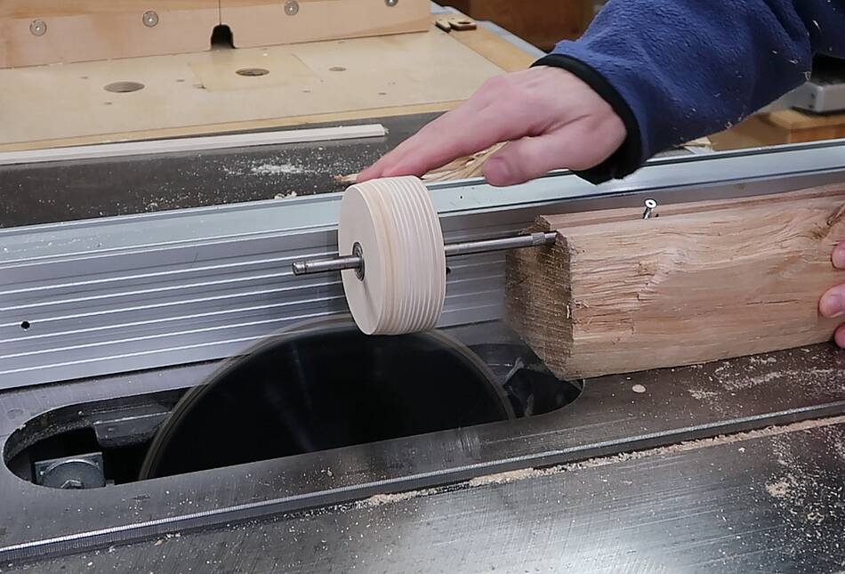
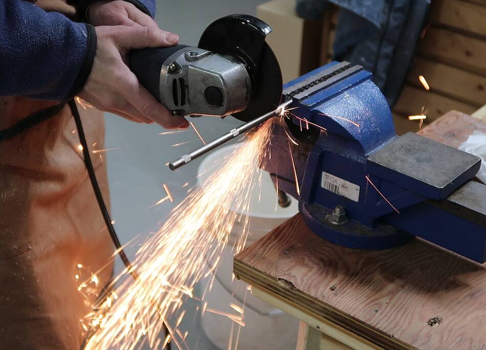
The bearings fit on an 8 mm shaft, which I got
out of an old printer. I cut a groove in a piece of firewood to rigidly
hold this shaft, placed the wheel on the shaft, and then spun it above
the blade on my table saw.
This would have looked much less dangerous if I hadn't taken out the table
saw insert (so more dust gets thrown into the saw), and used a less thick
block of wood so I wouldn't have had to raise the blade so high. A number
of people seemed alarmed when I posted this shot on
my Instagram
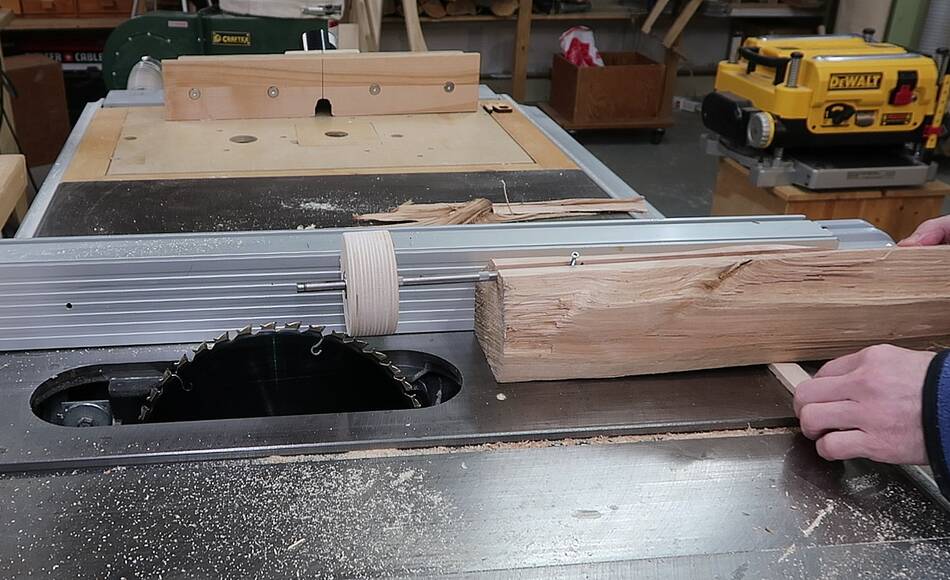
I raised the back of the block of wood to put the shaft at an angle
and cut from each side of the wheel to make a
"crowned wheel" for
one of the wheels, the other wheel is flat, and a third one yet to be made.
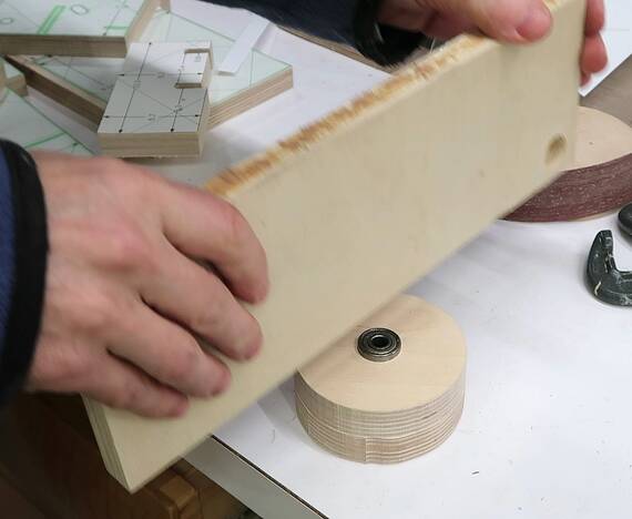
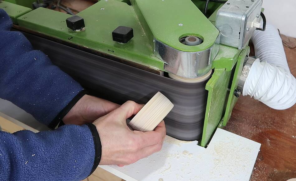
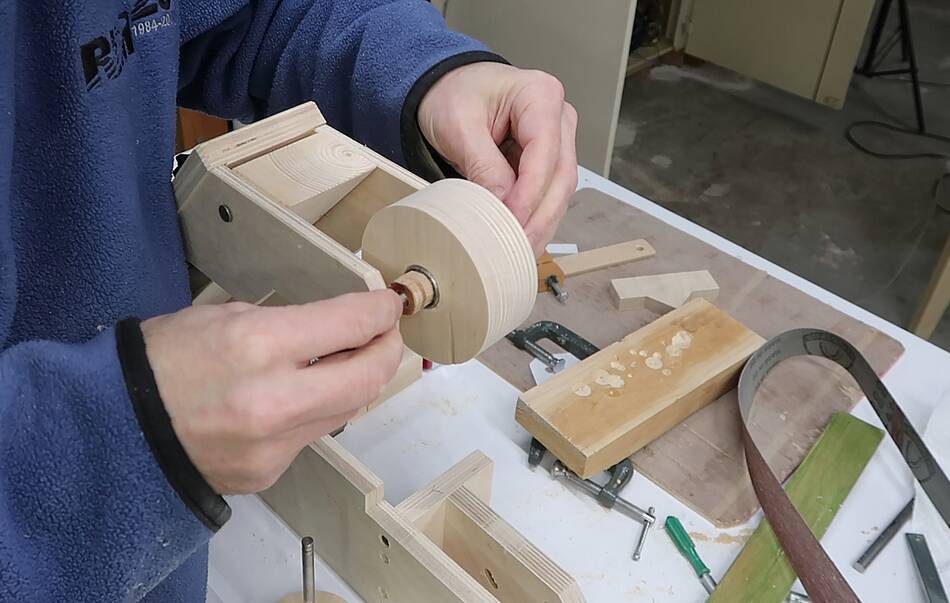
The table saw left the surface a bit rough, so I let the wheels spin
against my belt sander to smooth
the surface.
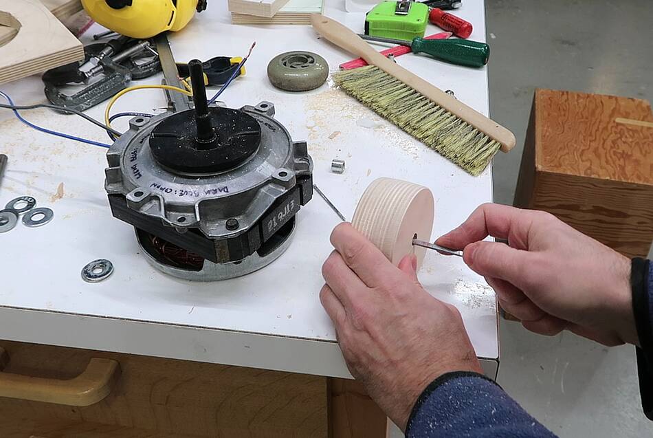
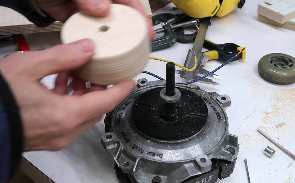
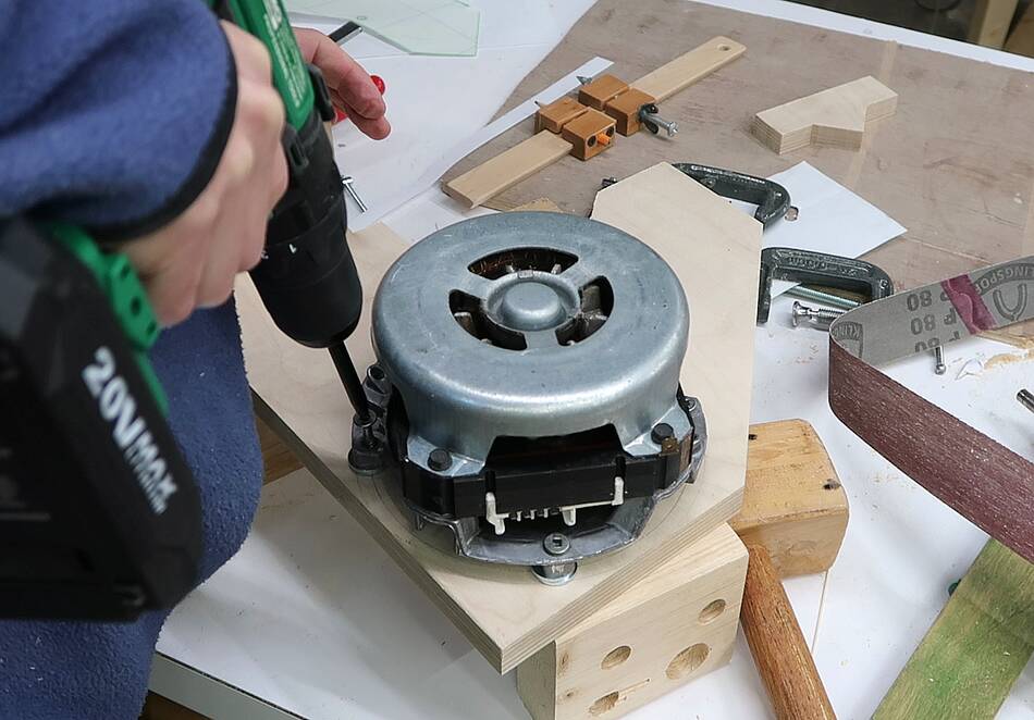
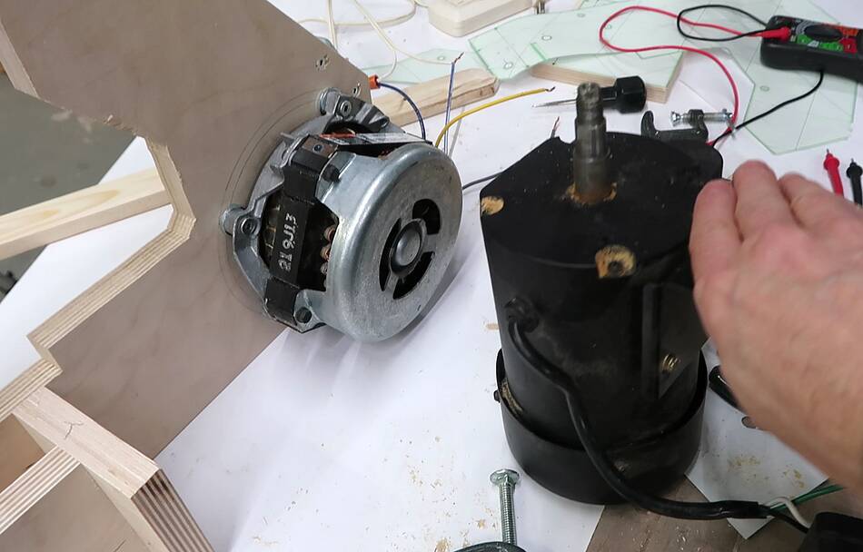
I made a third crowned wheel to fit on this dishwasher motor. The motor's
shaft is a bit larger than the 8 mm shaft I was using, so it fit rather
loose on it, but surprisingly, I was able to carve the wheel perfectly
shaped even with it loose on the shaft. I filed a notch in the drilled
hole to correspond with the flat surface on the shaft. My plan is to
put a screw in the space left by the flat spot on the shaft and the filed
notch to lock the wheel in place eventually.
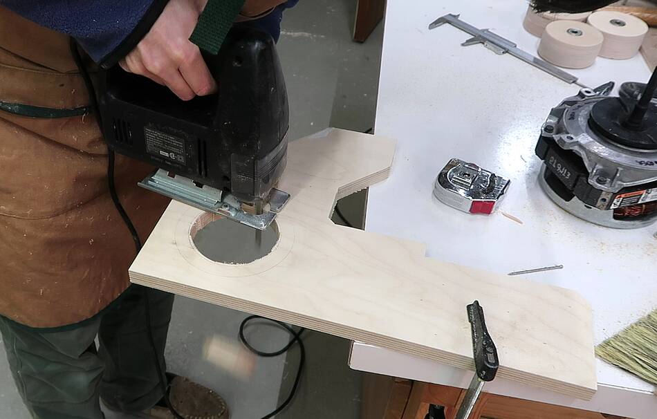
I want to be able to mount the wheel on the motor and leave it on the motor,
so I cut out a hole big enough to pass the wheel
through.
The wheel I made fit snugly on the shaft, but it was still possible to turn
it on the shaft without the locking screw in place. I'll add that later.
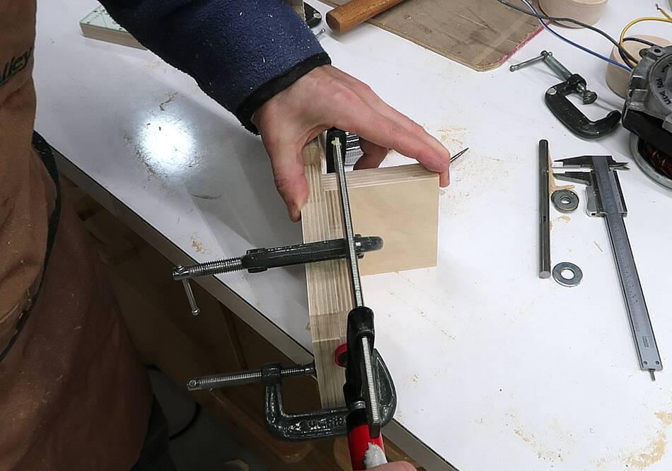
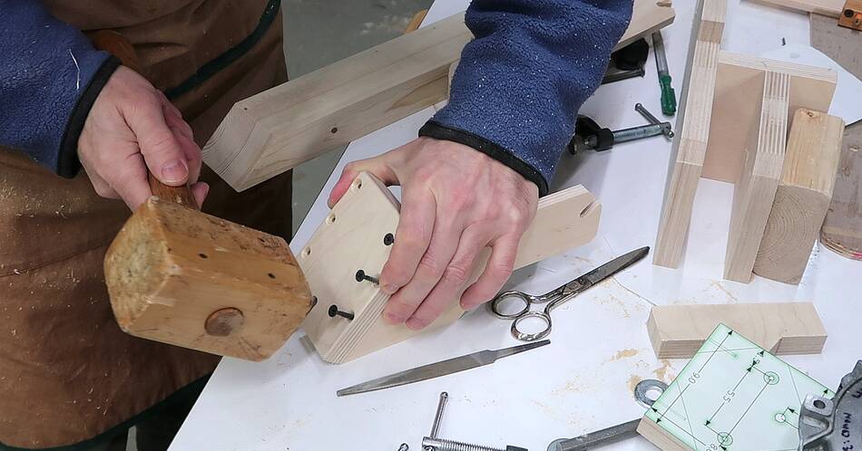
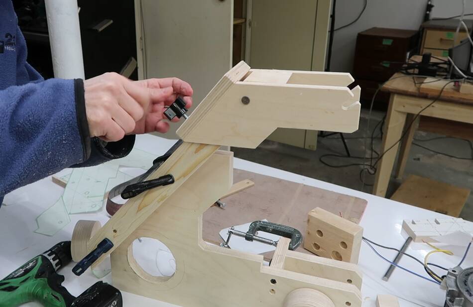
Jigging up some of the pieces for the sander to get the part alignment
worked out
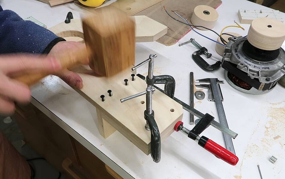
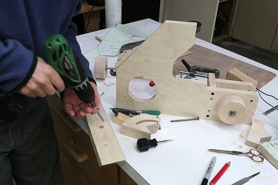
Then placing screws in the screw holes and tapping them with a hammer to
mark divots in the mating piece for where the pilot holes need to go.
A 9/64" hole precisely fits a #6 drywall screw.
I drilled 7/64" pilot holes for the screws.
Then screwing it together. This part will be where table mounts as well as
for the tracking adjustment device.
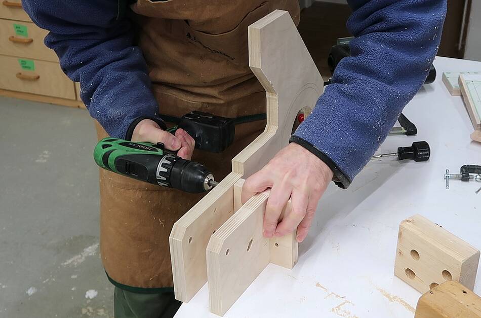
I used the same method to get the screw hole locations transferred for
the part that holds the upper wheel.
I then clamped the two pieces together with a block to help me hold
them at the right angle on my drill press.
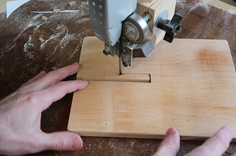
I now needed shorter pieces of shafting for the wheels so I cut apart
the longer shaft that I had used while shaping the wheels on
the table saw.
The longer piece holds the bottom wheel. The second piece this shaft
goes through has a diagonal slot in it to allow for tracking adjustment.
Unfortunately, that slot isn't visible in this photo.
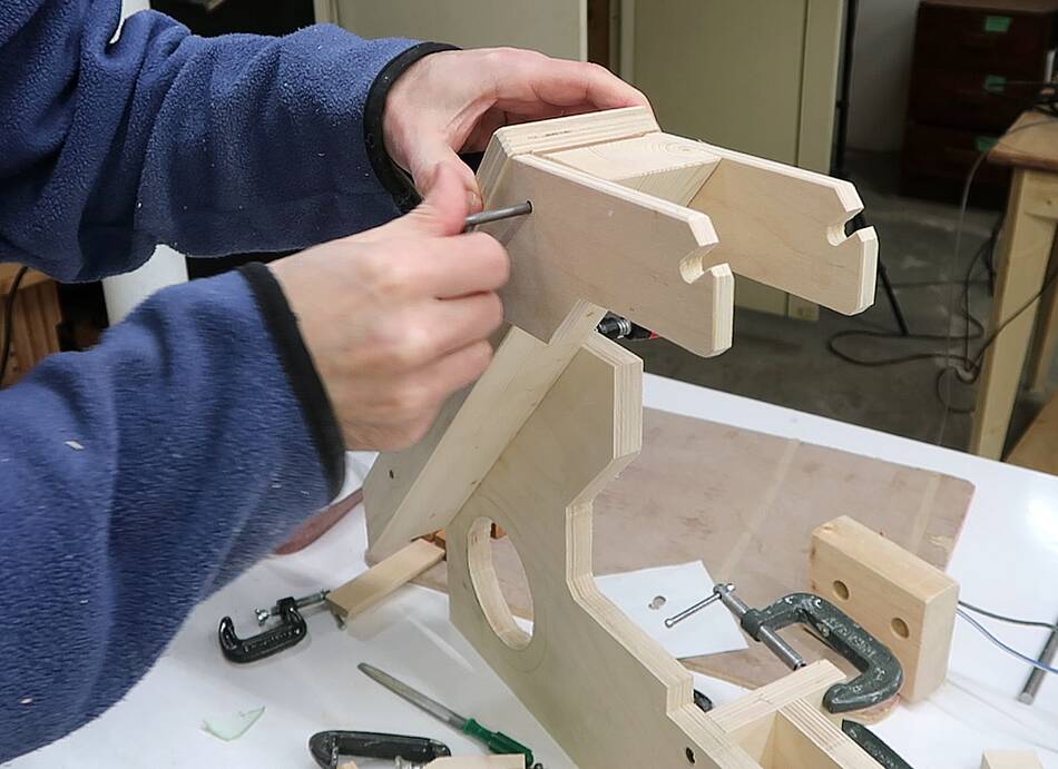
A pin joins the fork that holds the top wheel, This fork pivots on the
pin to tension the belt. The back of the fork needs to be pressed
down to apply belt tension.
I'm using a long 5/16" (similar to M8) bolt driven through a hole in
the back piece to apply tension.
A threaded knob on this bolt pushes down the back of the fork.
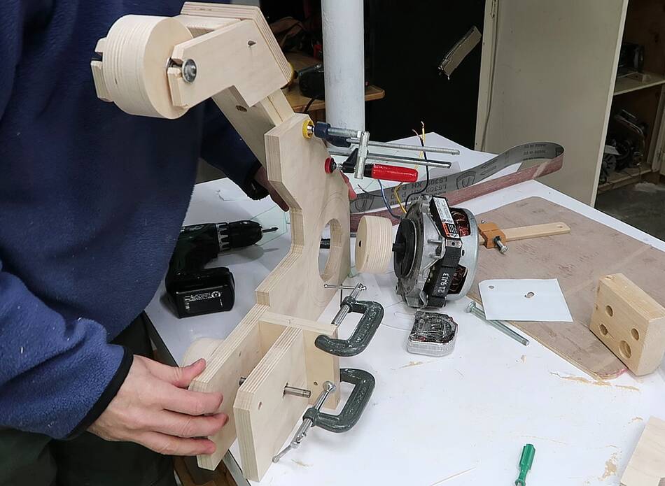
Now getting ready to add the motor.
But even before mounting the motor, I realized the belt is too short
for my sander. I made a mistake somewhere.
I was trying to figure out where I deviated from my CAD model to cause
this, but on further investigation, it turns out I had miscalculated
the belt length in my CAD model.
Fortunately, I was only off by a little bit, and adjusting the position
of the diagonal piece of wood for holding the top wheel fixed it.
I also corrected the CAD model after that.
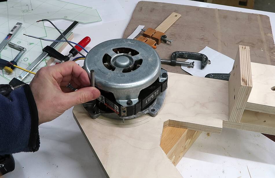
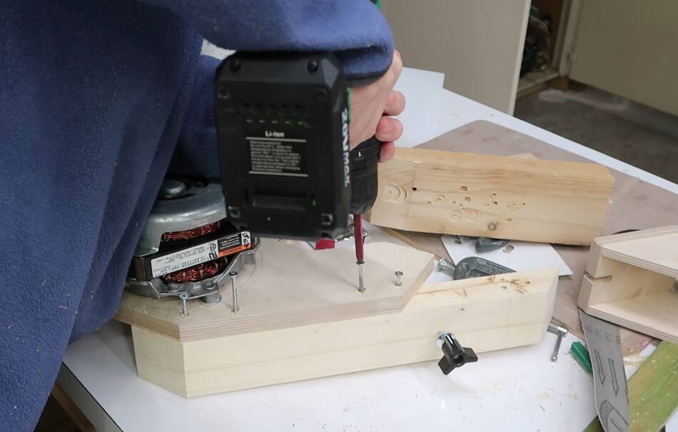
I drew some circles where the motor needs to go before I cut the hole
for the motor, and used that circle to position the motor. I then used
a brad point bit to transfer the marking hole locations onto the wood,
tapping the back of the drill with a mallet.
After drilling pilot holes, I used some #12 wood screws to mount the motor.
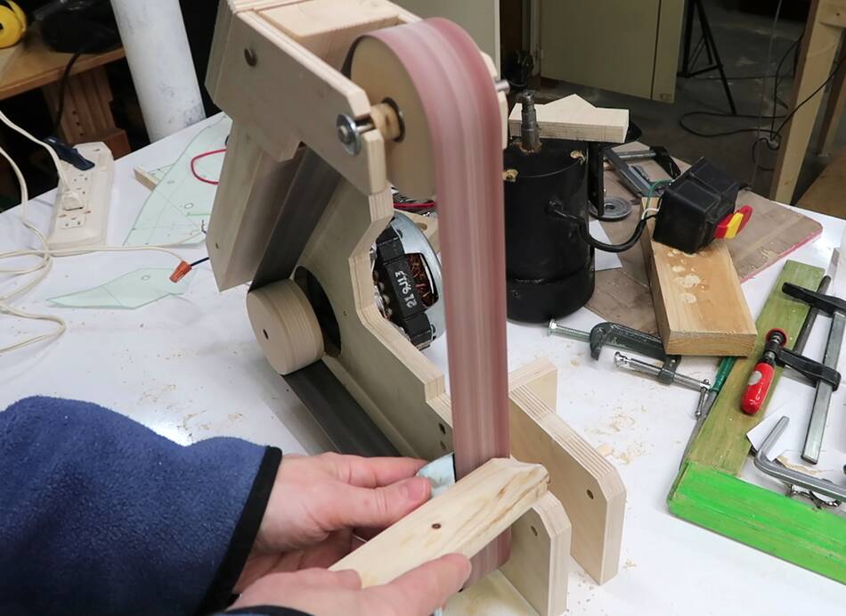
Then tweaking the upper wheel position to make sure the belt is vertical
at the front, and tensioned properly.
With the correct position established, I could screw that diagonal
piece onto the frame of the sander.
I made two small wooden spacers to keep the top wheel centered in the fork.
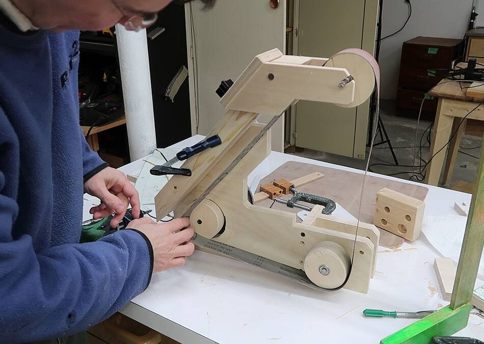
And then it was time to power it up. It works!
But it seemed that the sander was badly underpowered with this motor.
What to do?
I thought about switching to this 2/3 hp motor, but this motor spins in the
opposite direction and can not be reversed, so I would have to reassemble
the sander as a mirror image of itself to make it work. Also, the mounts
for this motor are completely different.
But then I realized that I had forgotten to lock the drive wheel to the motor
shaft. I screwed a small #4 screw into the notch of the wheel, against the
flat spot on the motor shaft. After that, the motor was adequate. Not
overly powerful, but sufficient.
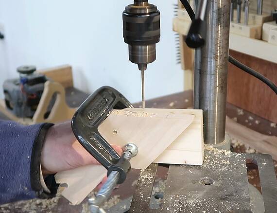
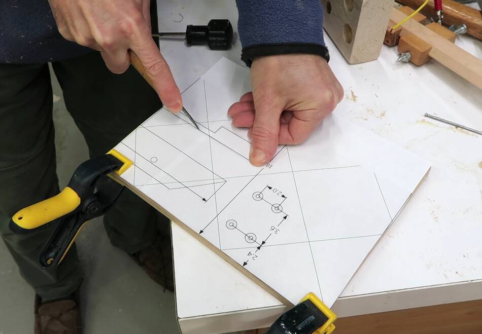
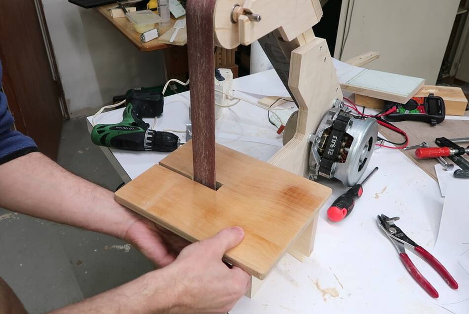
The next step was to build the table for the sander. I used my template to
mark the location of the cut out and screw holes.
Then cut it out on the table saw and bandsaw.
Checking the position on the sander
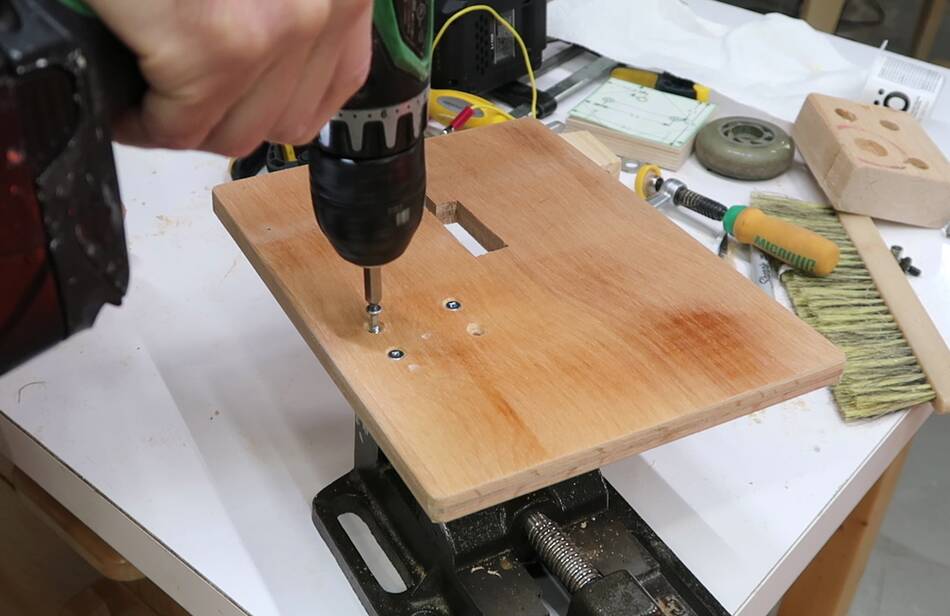
After drilling pilot holes in the table and table mount, I screwed it together.
A carriage bolt through the frame of the sander helps to pinch the mount
inside the frame to lock the table in place.
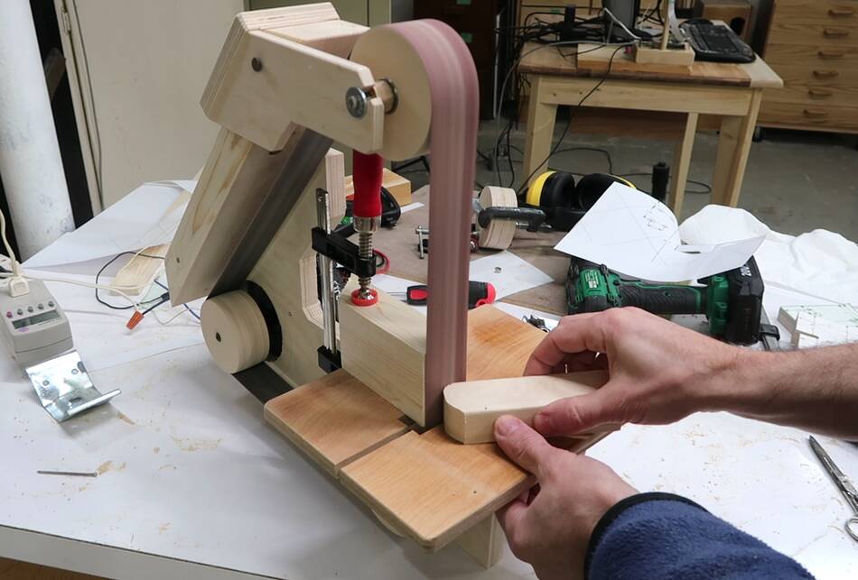
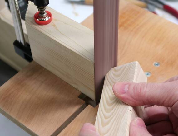
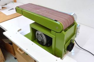
Testing it with the sander.
I still don't have a platen for it so I just clamped a block of wood to
the back of the table to help support the belt.
I still have a few things to do to finish it up, including:
* Platen
* Enclosure
* Dust port
* Base
* Electrical
* Painting it green
But I figured I will publish what I have now and work on that next.
 Ever since I built my strip sander
I quite like using it. I thought about building a second one,
but then I had the idea of building a bigger one using 1.5"x48" belts
instead of 1"x42" belts. I can cut these belts
from 6x48" sanding belts, especially sanding belts that are used up on my
6x48" belt sander
because there are usually some good parts of the belt left when
its done on that sander. Also a belt doesn't need to be as "sharp" for the kind
of use it gets on a strip sander.
Ever since I built my strip sander
I quite like using it. I thought about building a second one,
but then I had the idea of building a bigger one using 1.5"x48" belts
instead of 1"x42" belts. I can cut these belts
from 6x48" sanding belts, especially sanding belts that are used up on my
6x48" belt sander
because there are usually some good parts of the belt left when
its done on that sander. Also a belt doesn't need to be as "sharp" for the kind
of use it gets on a strip sander.


 6"x48" belt sander build
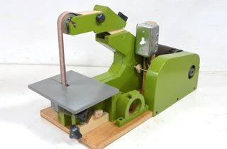 1"x42" strip sander build
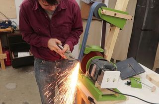 Belt grinder build
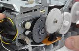 Tearing down an HP printer
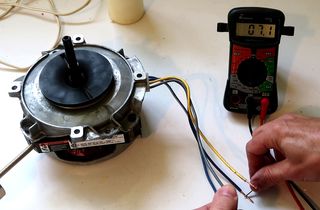 Figuring out the motor I used on this sander
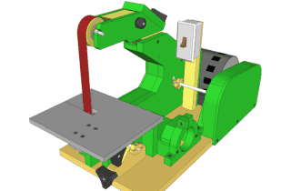 1.5"x48" Belt sander plans
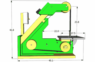 Specs for the 1x48" sander