 Having tried out the sander to make sure it works, it was time to finish
up a lot of the details.
Having tried out the sander to make sure it works, it was time to finish
up a lot of the details.
Having tried out the sander to make sure it works, it was time to finish
up a lot of the details.
The first thing was to make a cover for the big hole that I made so that the wheel on the motor could pass through it. This cover is to keep the dust from inside the sander out of the motor.
 In retrospect, the wheel is easy enough to get on and off the
motor shaft so keeping it on the motor wasn't necessary.
But some kind of cut-out would still have been necessary on the
motor side of the frame to make room for the fan blade on
the front of the motor.
In retrospect, the wheel is easy enough to get on and off the
motor shaft so keeping it on the motor wasn't necessary.
But some kind of cut-out would still have been necessary on the
motor side of the frame to make room for the fan blade on
the front of the motor.
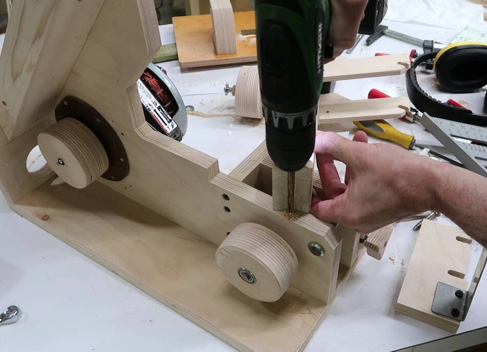
The motor's shaft has two flat spots. I'm using two small #4 screws to screw between the flat spots and v-notches that I filed at the side of the hole in the wheel. This makes for a simple but sturdy way to couple to wheel to the motor.
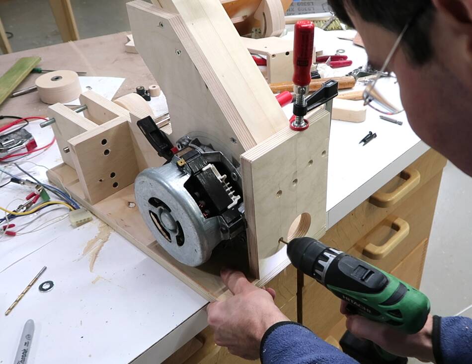
 Adding the base to the frame. I first drilled pilot holes for just two of
the screws, then put the first two screws in to line everything up
and drilled the pilot holes for the rest of the screws.
Adding the base to the frame. I first drilled pilot holes for just two of
the screws, then put the first two screws in to line everything up
and drilled the pilot holes for the rest of the screws.
The base is 18 mm "import" birch plywood, from China. It's a sort of imitation baltic birch plywood in that it's all thin birch layers like baltic, with voids, overlaps, and weaker glue.
 Screwing on the back plate. This was originally going to be further left
(towards the motor), but then I realized it would be better to extend it further
to the right to allow for more room for a dust port hole without getting that hole
too close to the edge. I realized that after I drilled the screw holes so I had
to drill another set of holes for the new position.
Screwing on the back plate. This was originally going to be further left
(towards the motor), but then I realized it would be better to extend it further
to the right to allow for more room for a dust port hole without getting that hole
too close to the edge. I realized that after I drilled the screw holes so I had
to drill another set of holes for the new position.
Checking alignment before I mounted it, I found the frame was leaning slightly to the right on the base and could not be pushed vertical. The motor was hitting the base, so I had to take the base off and drill a shallow relief hole for a corner of the motor.
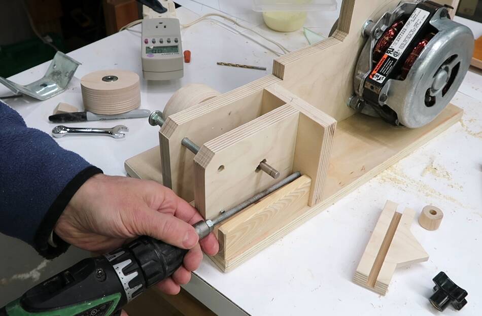
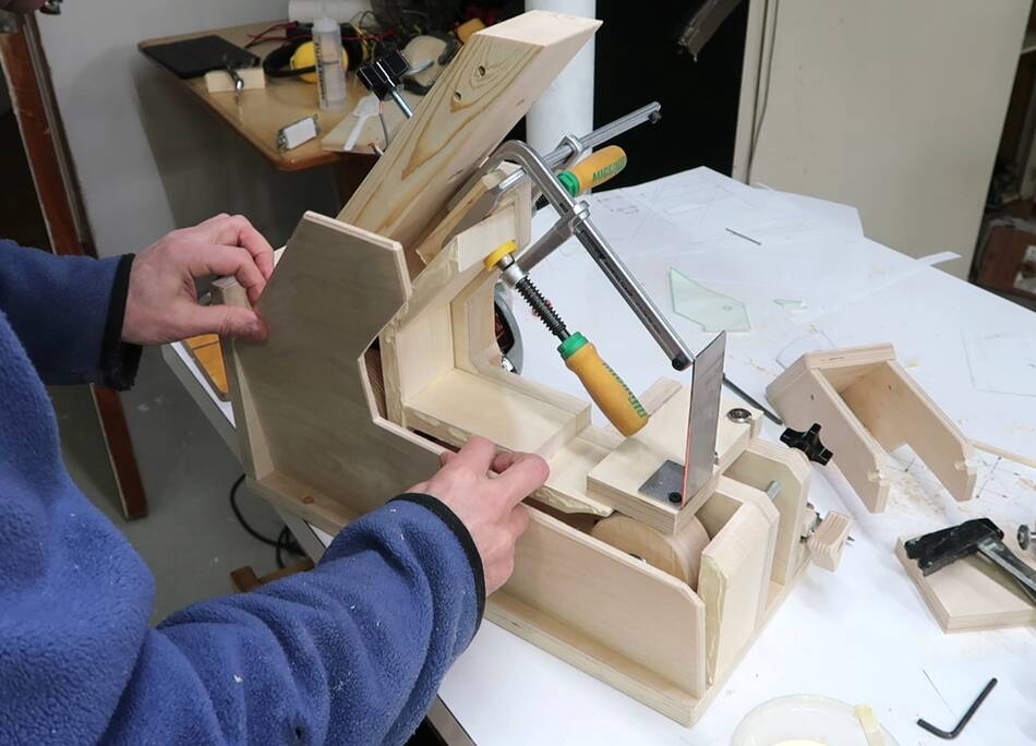
 The L-profile shaped piece I'm screwing on from the bottom here is to support
the part for adjusting tracking. When I hurriedly adjusted the CAD model for
the bigger sander design, I forgot to make this part deeper as I made the base
taller to accommodate bigger wheels. But it worked out well this way.
The L-profile shaped piece I'm screwing on from the bottom here is to support
the part for adjusting tracking. When I hurriedly adjusted the CAD model for
the bigger sander design, I forgot to make this part deeper as I made the base
taller to accommodate bigger wheels. But it worked out well this way.
Part of the problem with trying to avoid the latest virus is that the kids are home and so I don't have time to do as thorough a job as I used to.
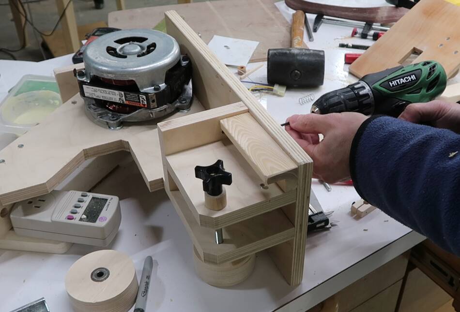
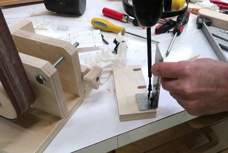
 The block with the bump on it (bottom right of the image) gets pushed back
by a knob on a threaded rod, which I'm screwing into the plywood here.
I have two nuts jammed against each other on the threaded rod and am
driving it into the wood with a nut driver on the drill.
The block with the bump on it (bottom right of the image) gets pushed back
by a knob on a threaded rod, which I'm screwing into the plywood here.
I have two nuts jammed against each other on the threaded rod and am
driving it into the wood with a nut driver on the drill.
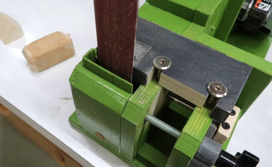
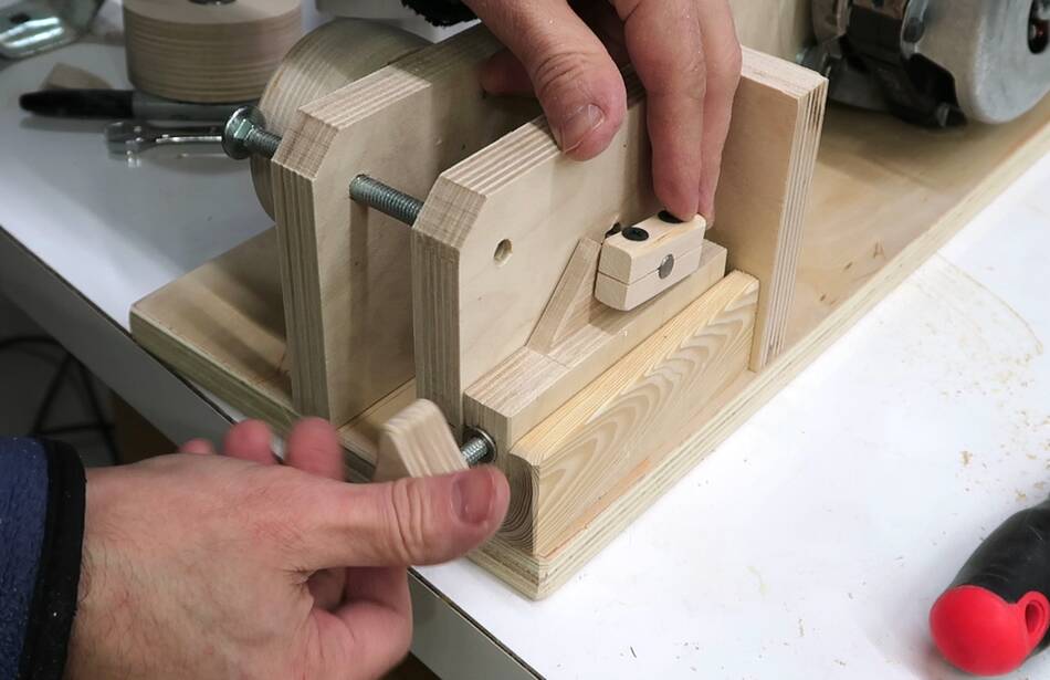 The tracking adjustment mechanism. The knob pushes the block with a bump on
it back, which pushes the end of the axle for the lower wheel back and
up in a slot, tilting the lower wheel. A block of wood clamped to the
end of that axle keeps the axle from slipping out.
The tracking adjustment mechanism. The knob pushes the block with a bump on
it back, which pushes the end of the axle for the lower wheel back and
up in a slot, tilting the lower wheel. A block of wood clamped to the
end of that axle keeps the axle from slipping out.
 Attaching the platen to the platen holder.
 I drilled and tapped two holes for the platen holder
 The platen holder is held down by two "knock down" type screws
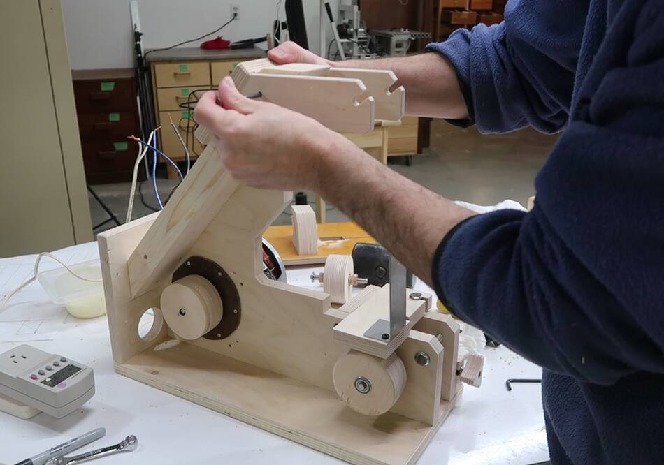 Inserting the pin for the top to pivot on. I temporarily used a big nail
with the intention of making a nice shaft with a knob on it like I did with the
last one, but then decided the nail was good enough, and that saves time.
Inserting the pin for the top to pivot on. I temporarily used a big nail
with the intention of making a nice shaft with a knob on it like I did with the
last one, but then decided the nail was good enough, and that saves time.
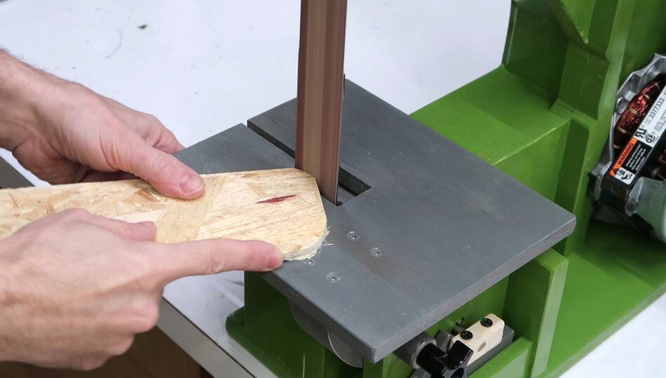
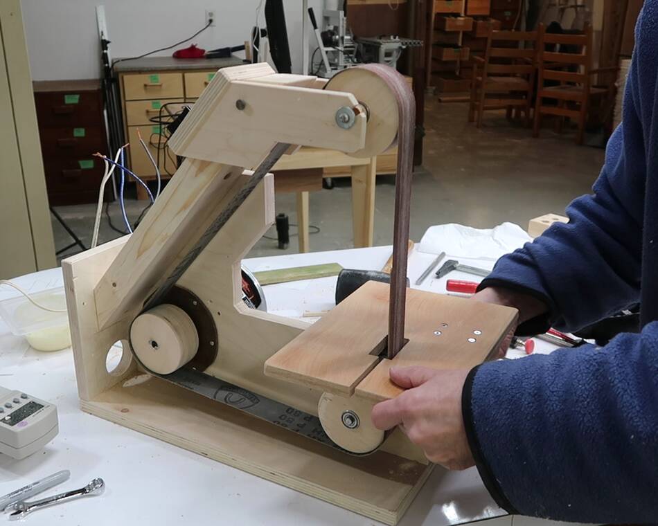 Mounting the table. My CAD model wasn't fully optimal in this regard and it turned
out better to mount the table further back, so I cut the slot for the belt a
little larger forward. I made appropriate adjustments in my CAD model
for making plans of it later, when I find the time.
Mounting the table. My CAD model wasn't fully optimal in this regard and it turned
out better to mount the table further back, so I cut the slot for the belt a
little larger forward. I made appropriate adjustments in my CAD model
for making plans of it later, when I find the time.
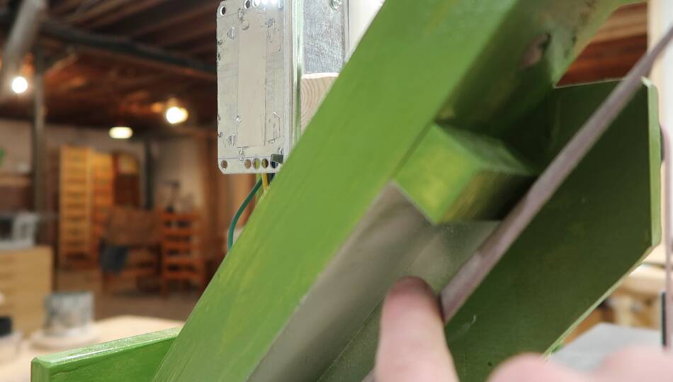
 With such a big hole in the frame for the drive wheel to pass through, I decided
to add a bit of extra reinforcement to the frame to stiffen it up.
With such a big hole in the frame for the drive wheel to pass through, I decided
to add a bit of extra reinforcement to the frame to stiffen it up.
This won't be part of the plans as it's shape and necessity is totally a function of motor size and type and whether you cut a big hole in the frame.
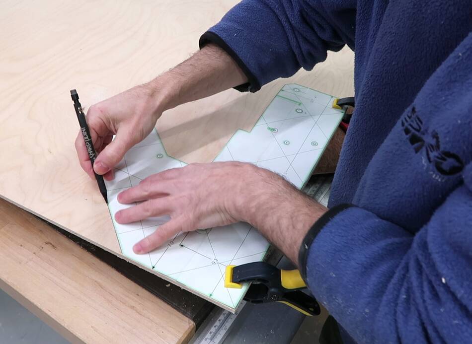 Even with my initial CAD model needing some adjustments, the shape of the frame
didn't change from what I printed, so I was able to use the paper template
I had left over from cutting out the frame to mark the profile for the
enclosure on some 1/4" baltic birch plywood.
Even with my initial CAD model needing some adjustments, the shape of the frame
didn't change from what I printed, so I was able to use the paper template
I had left over from cutting out the frame to mark the profile for the
enclosure on some 1/4" baltic birch plywood.
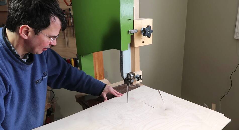 Then cutting it out on my 20" bandsaw.
The 20" size of this bandsaw is very handy when cutting out big parts from the
corner of a larger piece of plywood.
Then cutting it out on my 20" bandsaw.
The 20" size of this bandsaw is very handy when cutting out big parts from the
corner of a larger piece of plywood.
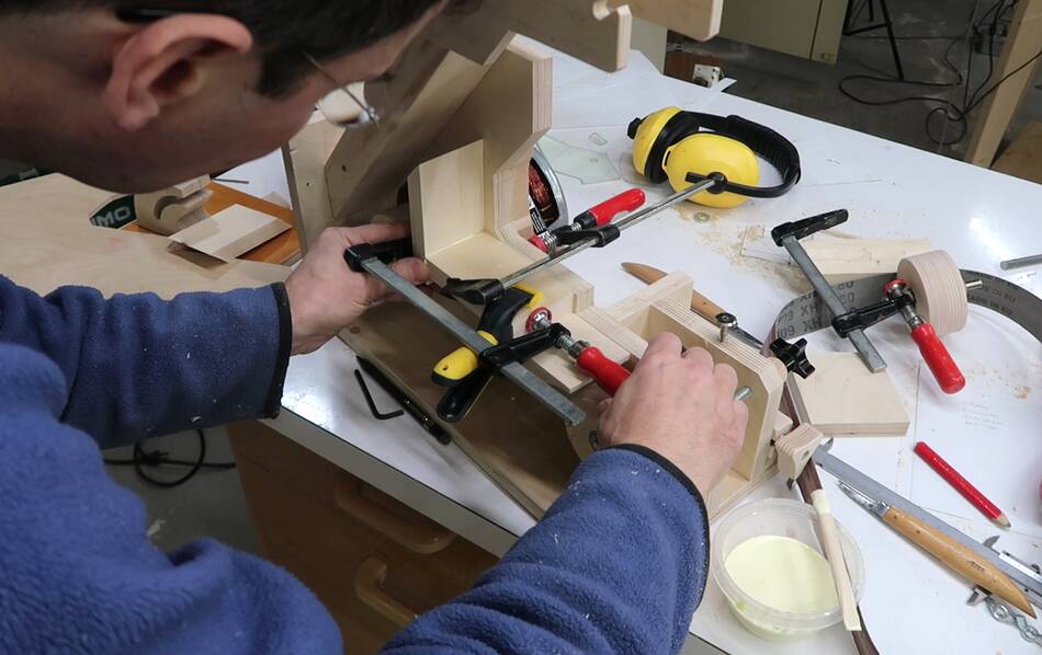 Next gluing together the inside part of the dust guard. I clamped these
against the frame while gluing them to each other, but not to the frame.
Next gluing together the inside part of the dust guard. I clamped these
against the frame while gluing them to each other, but not to the frame.
 After the glue dried, the pieces forming the inside of the sander's throat were
one unit, and I used two clamps to just hold them in place. I then applied glue...
After the glue dried, the pieces forming the inside of the sander's throat were
one unit, and I used two clamps to just hold them in place. I then applied glue...
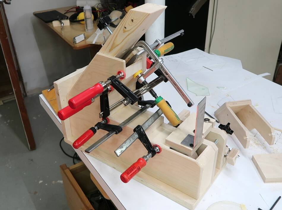 ... and then clamped the front of the dust cover against them.
I cut the throat of the dust guard a bit deeper than it was on the frame, seeing that strength wasn't a concern for the dust guard.
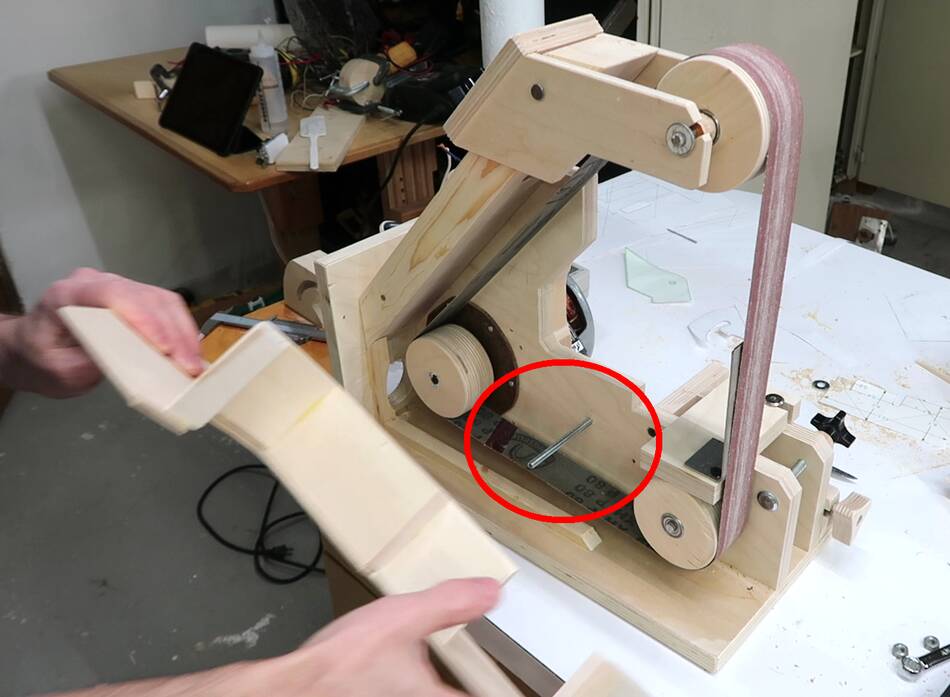 The dust guard is to be held in place with a wing nut that goes onto a piece of
threaded rod (circled in red). I marked where the hole for that needs to be
drilled in the cover by placing it against the threaded rod and tapping it
so the end of the rod left a mark.
The dust guard is to be held in place with a wing nut that goes onto a piece of
threaded rod (circled in red). I marked where the hole for that needs to be
drilled in the cover by placing it against the threaded rod and tapping it
so the end of the rod left a mark.
 I then drilled a hole where the mark was.
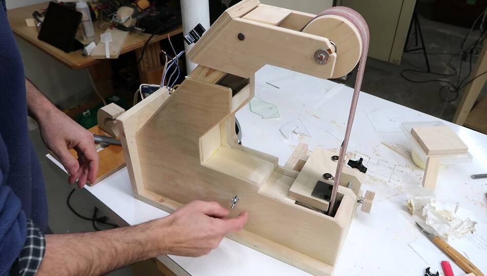 And putting it back on. Just one wing nut on this one. I used two on
my 1x42" sander, but one is enough.
And putting it back on. Just one wing nut on this one. I used two on
my 1x42" sander, but one is enough.
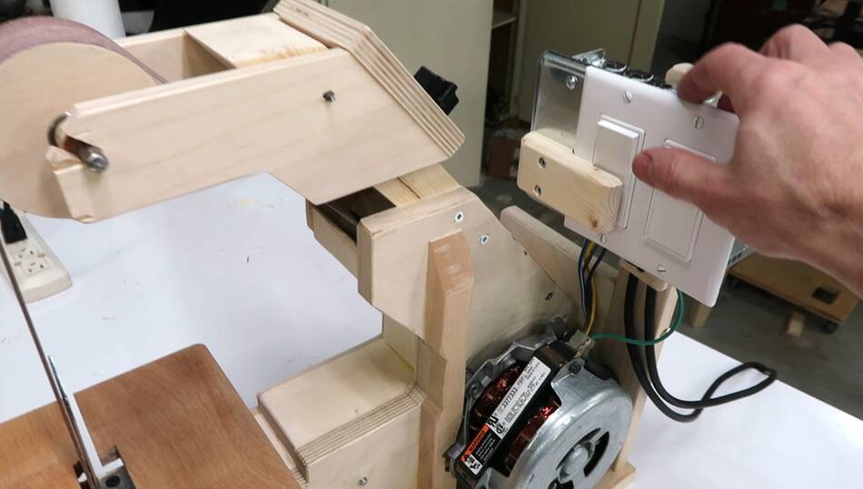 The on/off switch for the sander is a homemade NVR (no voltage reset)
switch, using a relay with an AC coil. I needed a momentary switch
for turning it on (holding the switch down engages the starter winding), but
could not find anything that I liked, or at least for a price I was willing
to pay. So the wooden thing against the bottom of the switch at left has a spring
behind it, effectively making the toggle switch a momentary switch.
The on/off switch for the sander is a homemade NVR (no voltage reset)
switch, using a relay with an AC coil. I needed a momentary switch
for turning it on (holding the switch down engages the starter winding), but
could not find anything that I liked, or at least for a price I was willing
to pay. So the wooden thing against the bottom of the switch at left has a spring
behind it, effectively making the toggle switch a momentary switch.
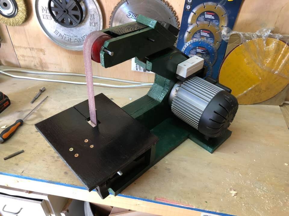
The sander is started by first switching the switch on the right on. This also powers up the socket for the sander. Then hold the switch at left for about half a second to engage the relay and the starter winding. A momentary interruption of power then resets the relay and stops the sander.
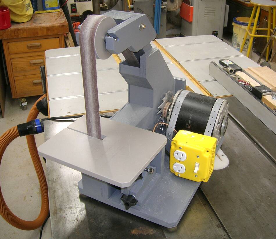
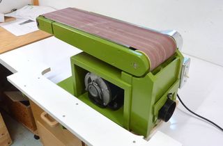
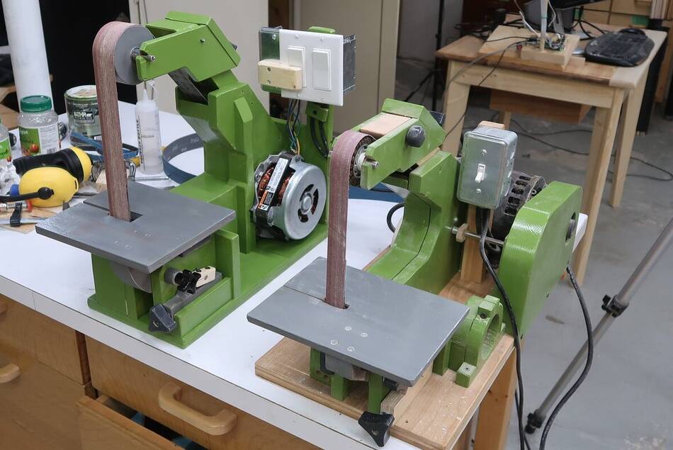 The new 1.5x48" sander next to my old 1x42" sander.
Thanks to the relatively flat direct drive motor the new larger sander has a smaller footprint than the older smaller sander.
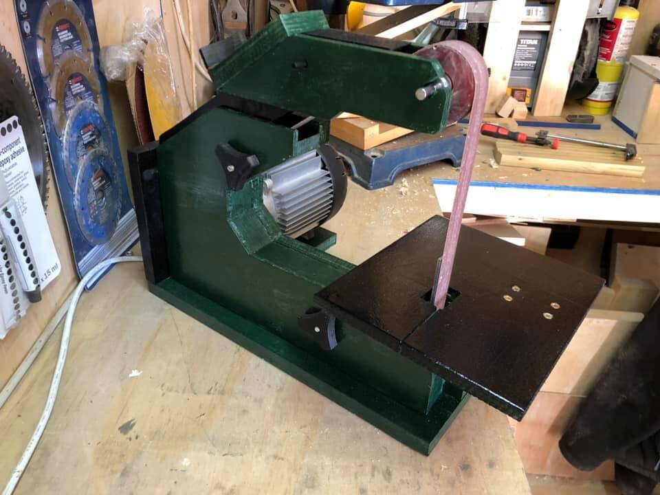
 Testing out the sander.
 I painted the inside of the enclosure green as well to make it easier to see where
the dust accumulates.
I painted the inside of the enclosure green as well to make it easier to see where
the dust accumulates.
There is some dust sticking to the enclosure going back from the bottom front wheel. I drilled a hole in the bottom front of the enclosure to get more air moving that way, but on re-testing it, that made no noticeable difference. But overall, I think it clears the dust well enough.
 I also added some blocks to the inside of the enclosure so that when its closed, the belt passes
through a relatively narrow slot before coming out to the top wheel. Looking at dust
accumulation, you can see dust sticking to the inside of the enclosure below this block,
but not above. Which suggests this method is fairly effective at containing the dust to
the inside of the machine so long as a dust collector sucks the air out of the back of the machine.
I also added some blocks to the inside of the enclosure so that when its closed, the belt passes
through a relatively narrow slot before coming out to the top wheel. Looking at dust
accumulation, you can see dust sticking to the inside of the enclosure below this block,
but not above. Which suggests this method is fairly effective at containing the dust to
the inside of the machine so long as a dust collector sucks the air out of the back of the machine.
 I also added a bit of a "lip" to the enclosure where the belt goes in. The idea is that it forces
more of the dust into the sander. And on inspection after some sanding, that area is totally clean,
so it looks like the dust for the most part goes into the sander.
I also added a bit of a "lip" to the enclosure where the belt goes in. The idea is that it forces
more of the dust into the sander. And on inspection after some sanding, that area is totally clean,
so it looks like the dust for the most part goes into the sander.
 Above: Leighton Gill's 1.5"x48" strip sander
Left: John Thames 1.5"x48" strip sander.
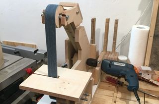
David Oakland's modified drill powered 1.5x48" strip sander
 6"x48" belt sander build
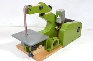 1"x42" strip sander build
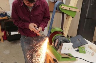 Belt grinder build
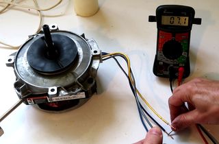 Figuring out the motor I used on this sander
 1.5"x48" Belt sander plans
 Specs for the 1.5x48" sander