 I drew up the initial CAD model for the pantograph in Google SketchUp, but to turn a CAD model
into a nice plan with dimensioned drawings takes a lot of time,
and I didn't want to do that until I was sure that my pantograph would work.
I drew up the initial CAD model for the pantograph in Google SketchUp, but to turn a CAD model
into a nice plan with dimensioned drawings takes a lot of time,
and I didn't want to do that until I was sure that my pantograph would work.
I drew up the initial CAD model for the pantograph in Google SketchUp, but to turn a CAD model
into a nice plan with dimensioned drawings takes a lot of time,
and I didn't want to do that until I was sure that my pantograph would work.
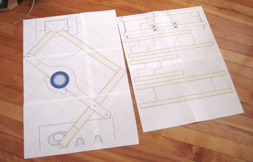 So I used my
BigPrint program to make multi-page
full scale printouts from the CAD model without labeling any of the
dimensions. With all sizes on even or half centimeters,
I could measure off the drawings to get the sizes.
So I used my
BigPrint program to make multi-page
full scale printouts from the CAD model without labeling any of the
dimensions. With all sizes on even or half centimeters,
I could measure off the drawings to get the sizes.
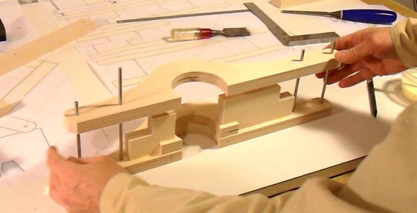
 I arranged all the curved parts together on one drawing, and cut
those out with the bandsaw.
I arranged all the curved parts together on one drawing, and cut
those out with the bandsaw.
I'm using 18 mm baltic birch plywood for the router mount, though other high quality plywood could also be used.
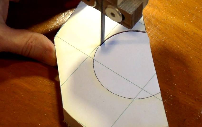 With a fine blade in a properly set up bandsaw, it's possible to follow
lines very closely. It's better to cut this with a bandsaw than
to use a circle cutter because with a circle cutter, if you get the
center position or radius just slightly off, the whole circle will
be off. Whereas if you go outside the line just briefly with the bandsaw,
it won't throw the whole circle off.
With a fine blade in a properly set up bandsaw, it's possible to follow
lines very closely. It's better to cut this with a bandsaw than
to use a circle cutter because with a circle cutter, if you get the
center position or radius just slightly off, the whole circle will
be off. Whereas if you go outside the line just briefly with the bandsaw,
it won't throw the whole circle off.
 The one-to-one scale drawings also came in handy to check the parts.
It was easy to make sure that I had produced all the parts
and to the correct size by arranging them on the drawing. So
I included more 1:1 views in the plans
I drew.
The one-to-one scale drawings also came in handy to check the parts.
It was easy to make sure that I had produced all the parts
and to the correct size by arranging them on the drawing. So
I included more 1:1 views in the plans
I drew.
I'm making the straight parts out of maple, though plywood could also be used for these.
 First I glued the router mount frame together without the top layer.
That way I didn't need to worry about getting everything aligned
all at once. The design of the router mount frame
is similar to the one I used for the
Pantorouter.
First I glued the router mount frame together without the top layer.
That way I didn't need to worry about getting everything aligned
all at once. The design of the router mount frame
is similar to the one I used for the
Pantorouter.
 I inserted 3/16" steel rods in all the holes when I was gluing it
together. That made it easy to keep it all aligned.
I inserted 3/16" steel rods in all the holes when I was gluing it
together. That made it easy to keep it all aligned.
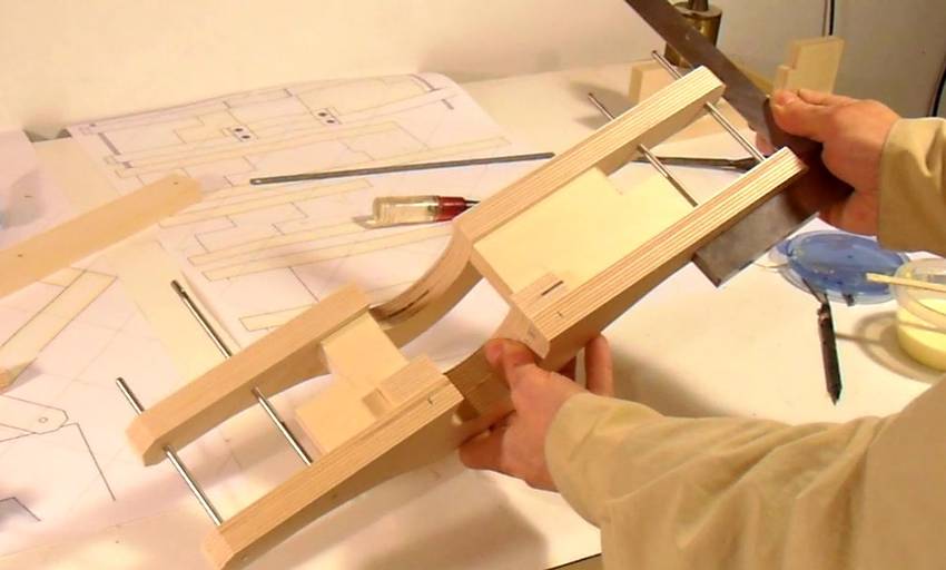 Checking the dry-fit for square-ness before putting it together with glue.
 Once the glue had dried for a few minutes I removed the 3/16 inch steel shafts.
I needed those to help align the other links as well.
Once the glue had dried for a few minutes I removed the 3/16 inch steel shafts.
I needed those to help align the other links as well.
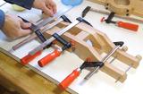
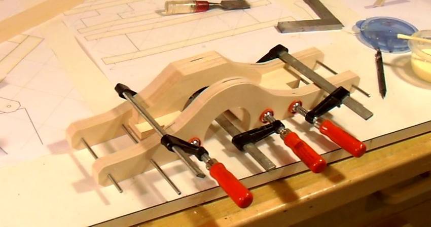
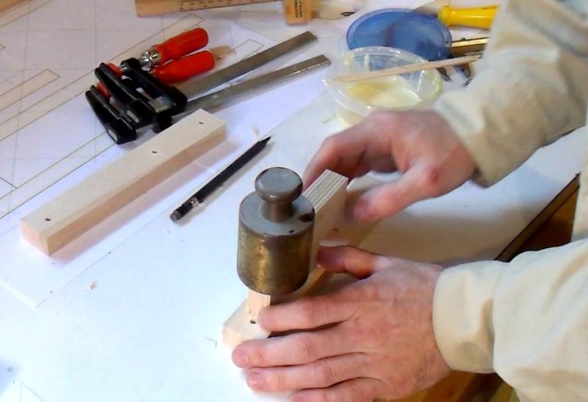 Wood glue is very slippery when wet, and applying clamps often
causes the parts to slide around a little. Using a weight instead of a clamp
avoids that problem.
Wood glue is very slippery when wet, and applying clamps often
causes the parts to slide around a little. Using a weight instead of a clamp
avoids that problem.
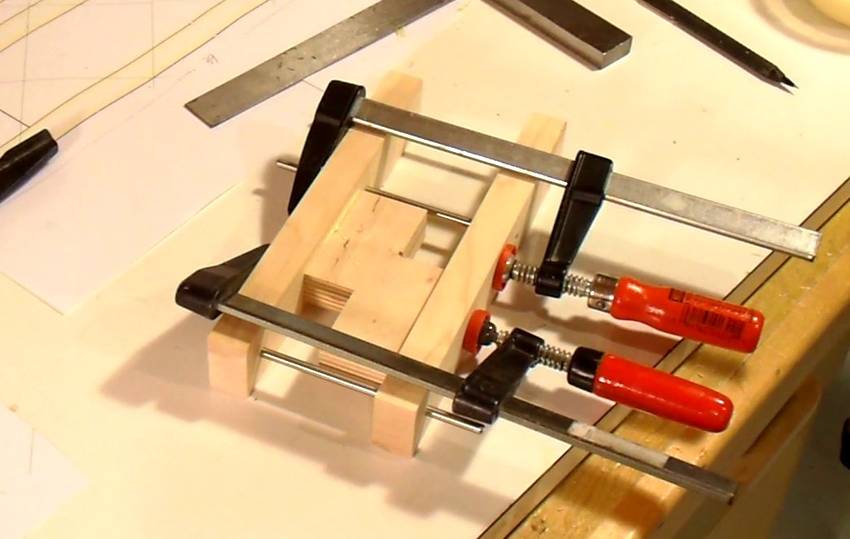 Again clamping it together with pins in place.
 I tried different 3/16" drills, and used the one that made for the
tightest fit with the shafts.
But once assembled, I found the holes a little too tight for my liking,
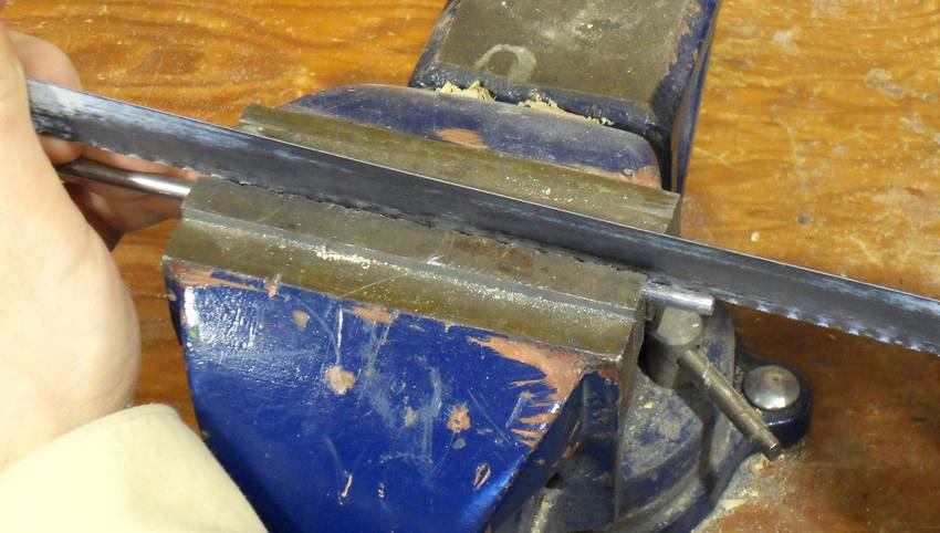
so I used one of my pieces of 3/16" shaft to make a sort of reamer.
I cut a slot in the end with a hacksaw.
I tried different 3/16" drills, and used the one that made for the
tightest fit with the shafts.
But once assembled, I found the holes a little too tight for my liking,
so I used one of my pieces of 3/16" shaft to make a sort of reamer.
I cut a slot in the end with a hacksaw.
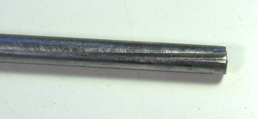 Experimenting with the reamer, I found that I could still ream holes up
to the right size even if they were drilled 1/64" (0.4 mm) too small.
So if your shafts are metric and your drills in inches, or vice versa,
you can drill one size smaller and then ream it out to the exact size.
Experimenting with the reamer, I found that I could still ream holes up
to the right size even if they were drilled 1/64" (0.4 mm) too small.
So if your shafts are metric and your drills in inches, or vice versa,
you can drill one size smaller and then ream it out to the exact size.
 If the holes don't end up perfectly aligned -- that is one of the holes
doesn't perfectly point at the other, the reamer can also be used
to bring them in line.
If the holes don't end up perfectly aligned -- that is one of the holes
doesn't perfectly point at the other, the reamer can also be used
to bring them in line.
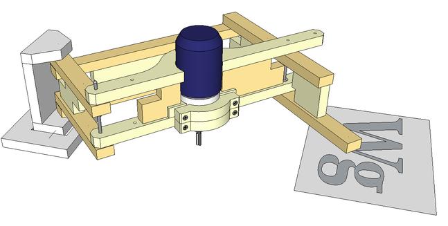
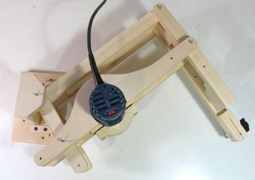
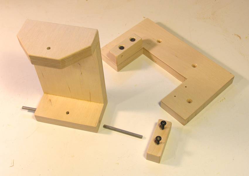 Here's the parts for the fixed mount. It tilts back and forth on a pivot.
This allows the endpoint of the pantograph to be lifted. With the pantograph
always supporting the weight of the router, even while cutting,
the router is always raised by a corresponding amount of the endpoint.
It's the rigid frame and pivoting back axis that makes this pantograph unique.
Here's the parts for the fixed mount. It tilts back and forth on a pivot.
This allows the endpoint of the pantograph to be lifted. With the pantograph
always supporting the weight of the router, even while cutting,
the router is always raised by a corresponding amount of the endpoint.
It's the rigid frame and pivoting back axis that makes this pantograph unique.
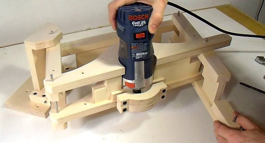 I used a "Bosch Colt" (also known as GKF 600) router, which is a palm router, or "laminate trimmer".
I built a mount for this router
for my Pantorouter.
I was still able to cut mortise and tenon joins with it, so I figured it
should be more than enough for this application.
I'm sure other smaller routers would work just as well. If you use other
sizes of router, you will have to draw a corresponding sized circle on the plans
with a compass.
I used a "Bosch Colt" (also known as GKF 600) router, which is a palm router, or "laminate trimmer".
I built a mount for this router
for my Pantorouter.
I was still able to cut mortise and tenon joins with it, so I figured it
should be more than enough for this application.
I'm sure other smaller routers would work just as well. If you use other
sizes of router, you will have to draw a corresponding sized circle on the plans
with a compass.
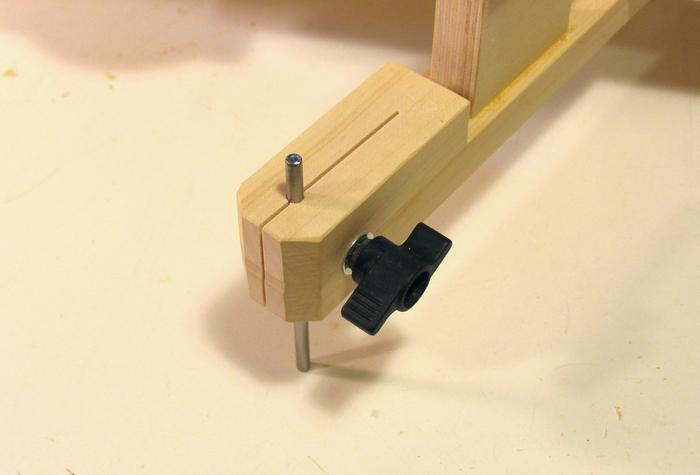 This is the end of the pantograph. It clamps a 3/16" steel rod. That way I can
make vertical adjustments, which is useful for making fine adjustments to the depth
of cut.
This is the end of the pantograph. It clamps a 3/16" steel rod. That way I can
make vertical adjustments, which is useful for making fine adjustments to the depth
of cut.
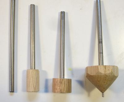 I made several followers for different applications, each on a piece of 3/16"
shaft.
For example, I use a conical shape
when carving 3-D letters. The middle two followers
are cylindrical to correspond to the size of the router bit, scaled according to how
much the pantograph scales by.
I made several followers for different applications, each on a piece of 3/16"
shaft.
For example, I use a conical shape
when carving 3-D letters. The middle two followers
are cylindrical to correspond to the size of the router bit, scaled according to how
much the pantograph scales by.
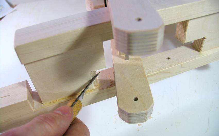 A few chamfers need to be cut to give the pantograph its full range of motion.
The easiest thing to do is to just carve them out with a knife after
the pantograph is assembled. That way there is no risk of
cutting them on the wrong spot or assembling it backwards. And believe me,
I struggle with that sort of thing too.
A few chamfers need to be cut to give the pantograph its full range of motion.
The easiest thing to do is to just carve them out with a knife after
the pantograph is assembled. That way there is no risk of
cutting them on the wrong spot or assembling it backwards. And believe me,
I struggle with that sort of thing too.
 This is the pantograph configured to scale to one half...
 And here it's configured to scale to one third.
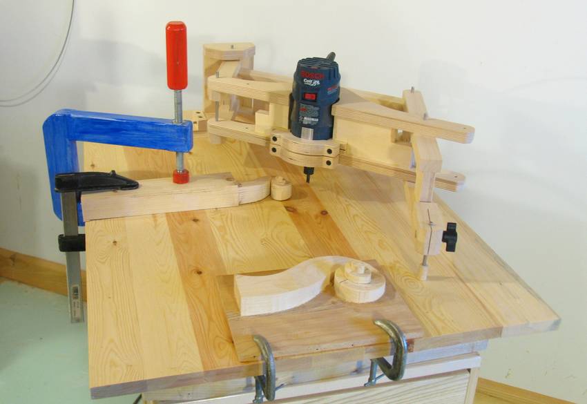 A wood panel or piece of plywood 60cm x 75cm (24" x 30") is ideal for mounting it.
Some long reaching clamps can also come in handy
for holding down the work piece. Of you can use wood screws to hold your workpiece down.
A wood panel or piece of plywood 60cm x 75cm (24" x 30") is ideal for mounting it.
Some long reaching clamps can also come in handy
for holding down the work piece. Of you can use wood screws to hold your workpiece down.
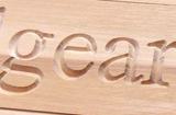 Carving 3-D letters